Displaying apparatus using data line driving circuit and data line driving method
A driving circuit and driving method technology, applied in static indicators, instruments, etc., can solve the problems of insufficient writing current, reducing contrast, increasing electric power consumption, etc., and achieve the effect of improving display unevenness and reducing chip area.
- Summary
- Abstract
- Description
- Claims
- Application Information
AI Technical Summary
Problems solved by technology
Method used
Image
Examples
no. 1 example
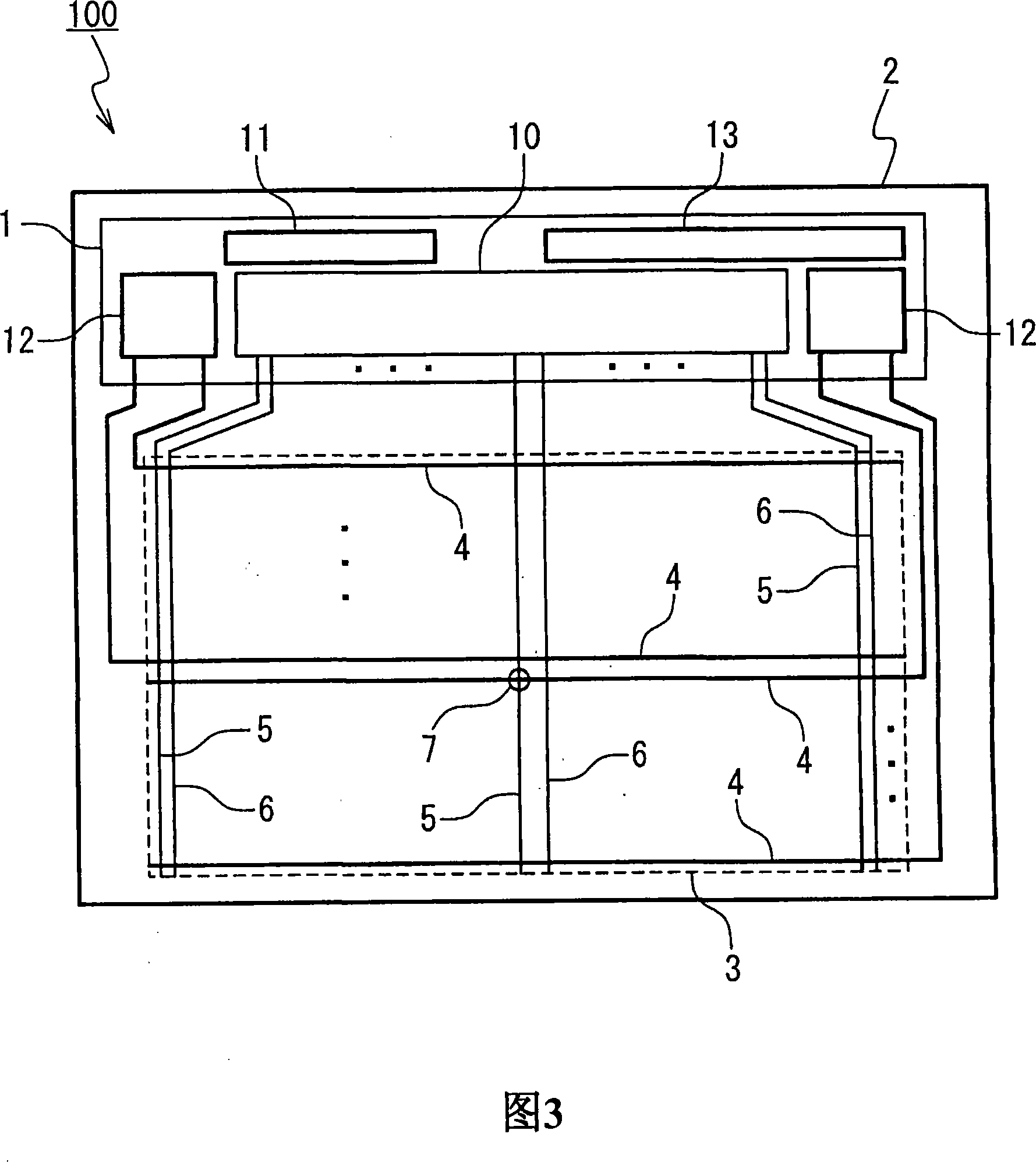
[0044] Next, a display device having a data line driving circuit according to a first embodiment of the present invention will be described with reference to FIGS. 3 to 7 . The display device 100 according to the first embodiment includes a data line driving circuit 10A as the data line driving circuit 10 shown in FIG. 3 .
[0045] FIG. 4 is a circuit diagram showing the configuration of a data line driving circuit 10A according to the first embodiment. The configuration of the data line driving circuit 10A according to the first embodiment will be described in detail with reference to FIG. 4 . The data line drive circuit 10A is a circuit that sends display signals to the pixels 7 through a plurality of data lines 5 and 6, and it includes at least: data latches 21 (21-1 to 21-4), multiplexers 22 (22 -1 to 22-4), D / A converter (DAC: digital-to-analog converter) 23 (23-1 to 23-4), buffer 24 (24-1 to 24-4), gray scale voltage generation Circuit 30 and time division switch group...
no. 2 example
[0071] Next, a display device having a data line driving circuit 10 according to a second embodiment of the present invention will be described with reference to FIGS. 3 and 8 to 11 . A display device 100 according to the second embodiment includes the same data line drive circuit 10B as the data line drive circuit 10 shown in FIG. 3 for dot back-driving on pixels 7 . Dot reverse driving is a driving method in which the polarities adjacent to the pixel 7 are different in the up, down, left, and right directions. In dot back driving, the voltage of the common electrode is usually fixed. Then, the data line driving circuit 10B inverts the polarity. In this embodiment, as an example, a case where the number of data lines in one group is three is described. Here, the number of data lines in a group is an odd number. Therefore, the number of data lines driven by one buffer 24 is 5 or 4. It should be noted that the number of data lines and the number of data lines driven by one ...
no. 3 example
[0104] Next, a data line driving circuit 10 according to a third embodiment of the present invention will be described with reference to FIGS. 3 and 12 , FIGS. 13A to 13G and FIG. 14 . A display device 100 according to the third embodiment includes a data line driving circuit 10C for performing dot reverse driving on pixels 7 , which is the same as data line driving circuit 10 shown in FIG. 3 . Dot reverse driving is a driving method in which the polarities of pixels 7 adjacent to each other in the up, down, left, and right directions are different. In dot back driving, the voltage of the common electrode is usually fixed. Then, the data line driving circuit 10C inverts the polarity. In this embodiment, as an example, a case where the number of data lines in one group is six is described.
[0105] FIG. 12 is a circuit diagram showing the configuration of a data line driving circuit 10C according to the third embodiment. Next, the configuration of a data line driving circu...
PUM
 Abstract
Description
Claims
Application Information
 - R&D
- Intellectual Property
- Life Sciences
- Materials
- Tech Scout
- Unparalleled Data Quality
- Higher Quality Content
- 60% Fewer Hallucinations
Browse by: Latest US Patents, China's latest patents, Technical Efficacy Thesaurus, Application Domain, Technology Topic, Popular Technical Reports.
© 2025 PatSnap. All rights reserved.Legal|Privacy policy|Modern Slavery Act Transparency Statement|Sitemap|About US| Contact US: help@patsnap.com


