Machine tool with linear guide device and linear guide replacement method

A working machine and replacement method technology, which is applied in the direction of tool replacement devices, metal processing machine parts, mechanical equipment, etc., can solve the problems of large moving amount and large gap, and achieve the effect of reducing working procedures and simple and cheap device structure

Inactive Publication Date: 2007-11-21
TOYOTA JIDOSHA KK +2
View PDF2 Cites 2 Cited by
  • Summary
  • Abstract
  • Description
  • Claims
  • Application Information

AI Technical Summary

Problems solved by technology

[0006] The structure disclosed in the above document is to insert the fixing bolt from the lower side of the linear guide and f

Method used


Image

  • Machine tool with linear guide device and linear guide replacement method
  • Machine tool with linear guide device and linear guide replacement method
  • Machine tool with linear guide device and linear guide replacement method

Examples


Embodiment Construction

[0024] Embodiments of the present invention will be described with reference to the drawings.

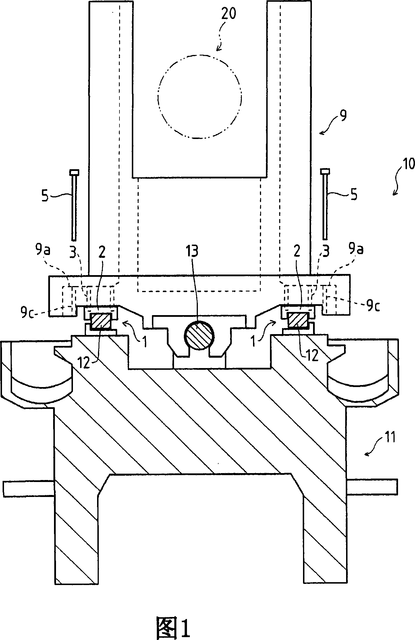
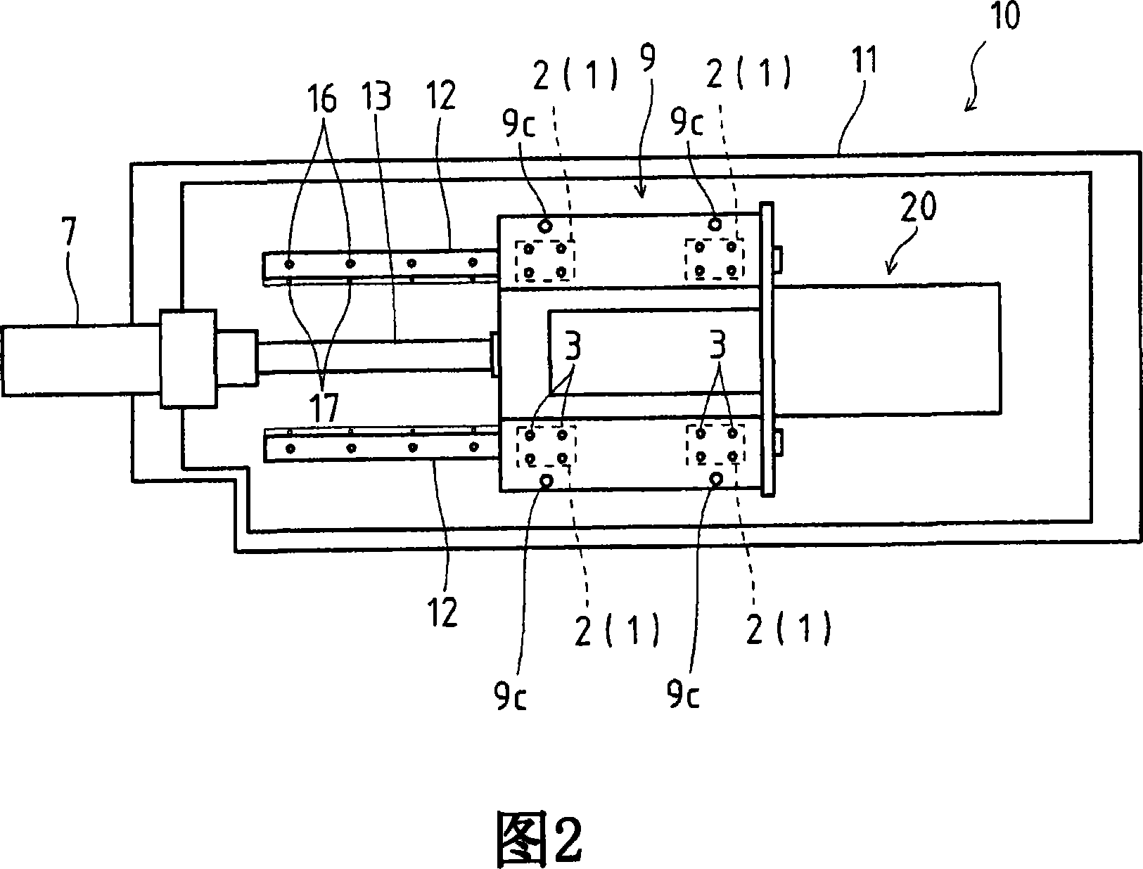
[0025] 1 and 2 are diagrams showing a machine tool 10 equipped with linear guide devices 1 and 1 according to the present invention. In FIG. On the guide rails 12, 12, the slide seat plate 9 as a moving body is provided via the linear guides 2, 2. In addition, a headstock 20 is attached to the slide seat plate 9 .

[0026] In addition, the sliding seat plate 9 moves in the left-right direction in FIG. 2 by the rotation of the ball screw 13 rotated by the motor 7 (refer to FIG. 2 ). 12 to guide the above-mentioned linear guides 2, 2 to perform linear motion.

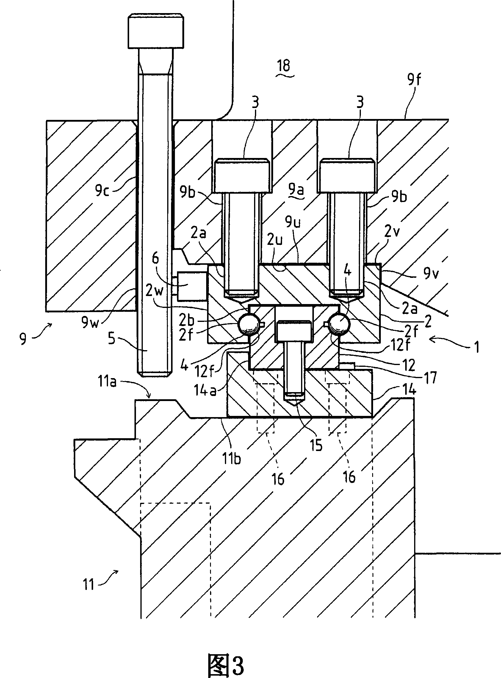
[0027] FIG. 3 is a diagram showing a specific structure of the linear guide device 1 according to the present invention, and a guide rail installation table 14 is fixedly mounted on the base 11 by fixing bolts 16 , 16 . Moreover, the guide rail 12 is fixedly mounted on the said guide rail installation stand 14 by the rail at...


PUM


Abstract

A machine tool with a linear guide device of a novel construction that enables simple linear guide replacement work. A machine tool is provided with linear guide devices (1, 1) having a base (11), guide rails (12, 12) placed on the base (11), linear guides (2, 2) movably placed on the guide rails (12, 12), and a jack up mechanism composed of a saddle (9)(movable body) movably supported by the guide rails (12, 12) with the linear guides in between and of a jack up bolt (5) provided between the base (11) and the saddle. The linear guides are fixed to the saddle through a fixation member. The fixation member is operated to release the fixation of the linear guides to the saddle, a gap (8) is formed between the saddle and the linear guides by using the jack up mechanism placed between the base and the movable body, and thereby the linear guides can be replaced.

Description

technical field [0001] The present invention relates to the technology of working machines such as machining centers, and more specifically relates to the technology of working machines having a linear guide device for linearly reciprocating a moving body such as a sliding seat plate along a guide rail . Background technique [0002] Conventionally, in working machines such as machining centers, a linear guide device is provided on a moving body such as a slide bed plate or a column, and the moving body is linearly reciprocated along a guide rail by the linear guide device. [0003] In addition, there are many documents disclosing the specific configuration of the linear guide device described above (for example, refer to Japanese Patent Laid-Open No. 2000-170761 and Japanese Patent Laid-Open No. 2003-56562). [0004] These documents disclose that the linear guide device is composed of a guide rail provided on a base, and a linear guide movably placed on the guide rail. In...

Claims


Application Information

Patent Timeline
IPC IPC(8): B23Q1/01
CPCY10T409/307728F16C29/02B23Q1/017Y10T483/10F16C29/004F16C2322/39
Inventor 石川俊一杉田真人松下贤治鸟居孝佳酒井浩一井上次郎杉原勉
Owner TOYOTA JIDOSHA KK
Why Eureka
Try Eureka