Anlenna device and method concerned

An antenna device and antenna section technology, which is applied in directions such as antennas, antenna arrays, and antenna components, can solve the problems of no antenna solution proposed and the reduction of scanning range gain.

Inactive Publication Date: 2007-11-21
TELEFON AB LM ERICSSON (PUBL)
View PDF0 Cites 14 Cited by
  • Summary
  • Abstract
  • Description
  • Claims
  • Application Information

AI Technical Summary

Problems solved by technology

However, the scanning range is also reduced due to grating lobes that produce reduced gain as well as reduced spatial filtering, which is a disadvantage
[0004] Therefore, no satisfactory solution has been proposed so far in relation to the problem of providing an antenna which is satisfactory, e.g. from a coverage or gain point of view

Method used


Image

  • Anlenna device and method concerned
  • Anlenna device and method concerned
  • Anlenna device and method concerned

Examples


Embodiment Construction

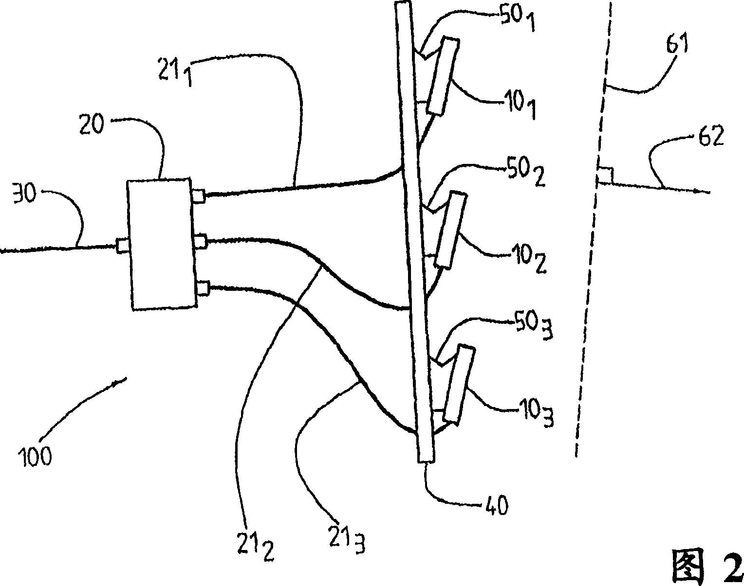
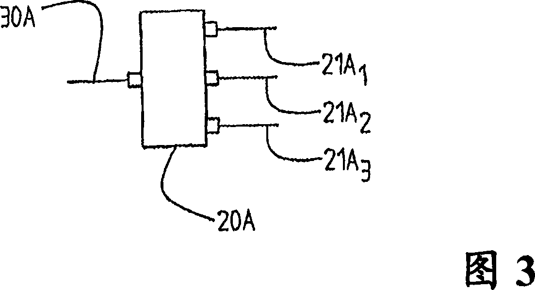
[0049] To further understand this document, a brief description of the terms used is given. Herein an antenna element means an individual radiating element; however, the term "radiating element" is primarily used in this document. A sub-array here means a group of antenna elements, ie radiating elements, which are arranged in a certain relationship to each other. They are usually arranged in a straight line with equal or unequal spacing between the corresponding antenna elements or radiating elements. An antenna section is a physical unit. For example, it may be an off-the-shelf antenna or an antenna section specially manufactured to provide a multi-section antenna. Antenna sections can generate one or more beams, such as dual polarized antennas. Specifically, each beam has an RF connector. The antenna sections may be commercially available antennas such as sector antennas with azimuth beamwidths of 45°, 60° or 90°. However, it can also be a specially designed antenna sec...


PUM


Abstract

An apparatus for treating waste includes a vessel and DC and / or AC plasma torches with a variable flame mounted with the vessel. The flames generated by the torches can be adjusted depending on the characteristics of the waste being treated. Waste can be introduced into the vessel and heated with energy from the flame. The energy can melt or vitrify the inorganic portion of the waste and gasify and dissociate the organic portion of the waste. This dissociation can destroy the hazardous or toxic constituency of the waste.

Description

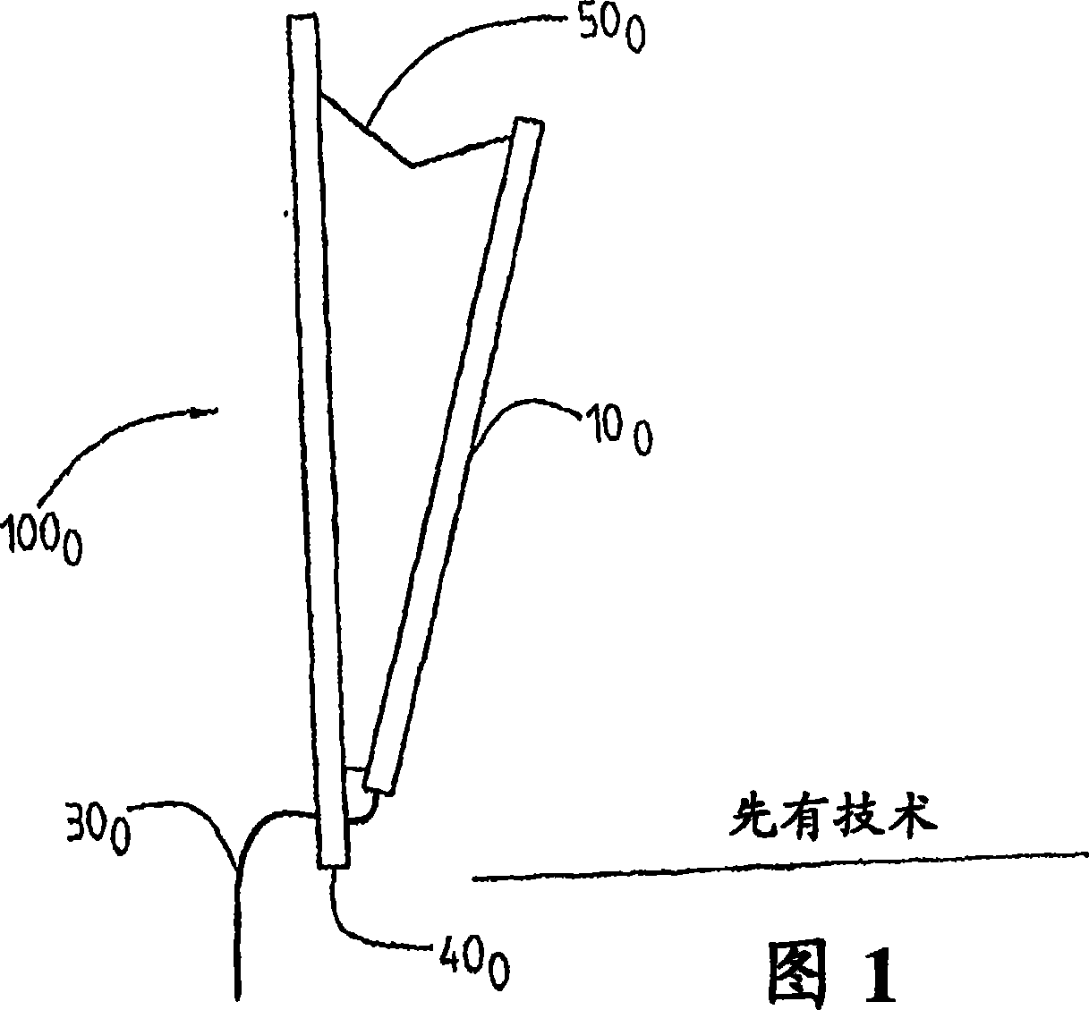
technical field [0001] The invention relates to an antenna arrangement comprising an antenna section with a plurality of radiating elements arranged in sub-arrays. The invention also relates to a method for controlling beamforming in an antenna arrangement comprising an antenna section which in turn comprises a plurality of radiating elements which may be arranged in a sub-array. Background technique [0002] The antennas used today on radio base stations of cellular mobile communication systems are often of the sectoral type. Three, six or more such antennas together cover 360 degrees in azimuth. It is generally desirable to be able to extend the coverage of a radio base station. But a high-gain antenna is required. In general, the longer the antenna mechanically, the easier it is to provide higher gain without changing the azimuth beamwidth. However, even though mechanically longer antennas are attractive for the reasons described above, there are several disadvantages...

Claims


Application Information

Patent Timeline
Patent Type & Authority Applications(China)
IPC IPC(8): H01Q21/00
CPCH01Q21/0018H01Q1/246H01Q3/26H01Q3/32
Inventor A·德纳伊德S·彼得森S·约翰逊M·N·约翰逊
Owner TELEFON AB LM ERICSSON (PUBL)
Why Eureka
Try Eureka