
Board joint method of dual-side printed circuit board

A printed circuit board and double-sided printing technology, which is applied in the direction of assembling printed circuits, electrical components, electrical components, etc., can solve the problems of waste, low production efficiency, and time-consuming, etc., to reduce production costs and simplify Mounting process, the effect of improving production efficiency

Active Publication Date: 2007-11-28
MAIPU COMM TECH CO LTD
View PDF0 Cites 15 Cited by
  • Summary
  • Abstract
  • Description
  • Claims
  • Application Information

AI Technical Summary

Problems solved by technology

The number of stencils is large, and the purchase cost is high. The top and bottom components need to be fed to the feeder separately. It takes a lot of time to center the stencil and change the material of the feeder. It will cause waste when placing and collecting solder paste, and the production efficiency is low.

Method used


Image

  • Board joint method of dual-side printed circuit board
  • Board joint method of dual-side printed circuit board

Examples


Embodiment

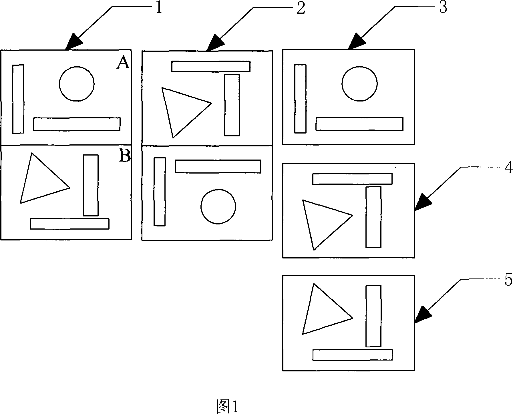
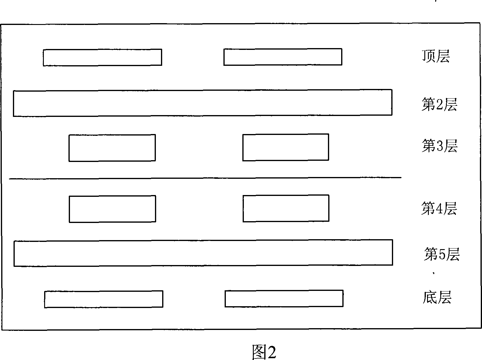
[0031] See Figure 1. In the figure, figure 3 is the bottom figure of the printed circuit board with smaller size, figure 4 is the top layer figure of the printed circuit board with smaller size, and figure 5 is the mirror image of figure 4 in the horizontal direction. In the figure, place figure 3 at position A, and figure 5 at position B, that is, figure 3 and figure 5 are spliced ​​horizontally (the splicing direction can be determined according to the printed circuit board) to obtain figure 1, which constitutes a larger printed circuit board Figure 1 is mirrored in the horizontal direction to obtain Figure 2, which is the bottom layer figure of the larger printed circuit board.

[0032] In Fig. 1, only the splicing situation of producing two smaller-sized double-sided printed circuit boards at a time is shown. According to the splicing method described above, larger printed circuit boards can be obtained, and more smaller printed circuit boards can be produced at one time....


PUM


Abstract

This invention discloses a method for splicing PCB including the following steps: a, imaging a small sized top graph of a PCB, b, splicing a small sized bottom graph of the PCB with the image got in step a to a large sized top graph image of the PCB, c, taking the image got from step b as the bottom graph of said PCB, which greatly simplifies surface adhering technical flow of PCB to increase production rate and reduce cost of production.

Description

technical field [0001] The invention relates to a surface-mounting production process of a printed circuit board, in particular to a jigsaw method for a printed circuit board. Background technique [0002] The speed of individualized development of electronic products is getting faster and faster, and the production of small batches of multiple varieties has raised new issues for the assembly of electronic product components - reducing the time for variety switching and improving production efficiency. [0003] In order to improve production efficiency, when the electronic product manufacturing industry carries out surface mount production of small-sized printed circuit boards, it usually splices multiple printed circuit board graphics into a larger-sized printed circuit board graphic. After completing the relevant mounting process , and crop it. Such a process cycle can produce multiple printed circuit boards with smaller sizes. [0004] For double-sided printed circuit b...

Claims


Application Information

Patent Timeline
Patent Type & Authority Applications(China)
IPC IPC(8): H05K13/00H05K3/36
Inventor 郭凯陈灿
Owner MAIPU COMM TECH CO LTD
Learn More