Wire harness separator assembly, method of assembling same, battery and device

An assembly method and isolation board technology, which is applied in the manufacture of batteries, battery pack parts, secondary batteries, etc., can solve the problems of long time consumption, low production efficiency, cumbersome assembly process of wire harness isolation board components, etc., and simplify the placement process , the effect of improving production efficiency

Active Publication Date: 2021-04-06
JIANGSU CONTEMPORARY AMPEREX TECH LTD
View PDF6 Cites 0 Cited by
  • Summary
  • Abstract
  • Description
  • Claims
  • Application Information

AI Technical Summary

Problems solved by technology

The assembly process of the entire wiring harness isolation plate assembly is cumbersome, time-consuming and low in production efficiency

Method used


Image

  • Wire harness separator assembly, method of assembling same, battery and device
  • Wire harness separator assembly, method of assembling same, battery and device
  • Wire harness separator assembly, method of assembling same, battery and device

Examples


Embodiment 1

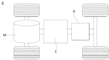
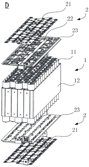
[0041] Embodiment 1 of the present application provides a battery D, especially an assembly method of the wire harness separator assembly 2 in the battery D, and a device using the battery D as a power source.

[0042] Devices that use the battery D as a power source include vehicles A, ships, small aircraft, etc. The device uses the battery D to provide electrical energy to generate driving force for driving the device. The device can also use electricity and other types of energy (such as fossil energy) at the same time to generate driving force. All devices that can use the battery D as a power source are within the protection scope of the present application.

[0043] figure 1 It is a schematic diagram of the structure of the vehicle in Embodiment 1 of the present application.

[0044] Such as figure 1 As shown, taking vehicle A as an example, vehicle A in the embodiment of the present application may be a new energy vehicle, and the new energy vehicle may be a pure ele...

Embodiment 2

[0091] The present application also provides an assembly method of the wire harness separator assembly 2 of the battery D.

[0092] Figure 14 It is a flow chart of the assembly method of the wire harness isolation board assembly according to the second embodiment of the present application. In this embodiment, the parallel connection of the battery cells 11 is taken as an example for illustration.

[0093] Such as Figure 14 As shown, the assembly method of the wire harness isolation plate assembly 2 of the present application includes the following steps:

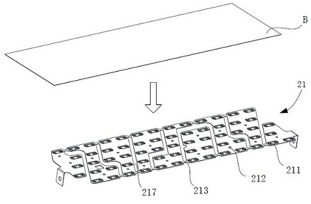
[0094] In step S1 , the plate B is integrally formed into a busbar set 21 , wherein the busbar set 21 includes a plurality of busbar units 212 and a connecting portion 213 connecting the plurality of busbar units 212 to each other.

[0095] In step S1 , first select a plate B of a suitable size according to the arrangement of the battery cells 11 , and then cut the plate B according to the connection method of the batt...


PUM


Abstract

The present application provides an assembly method of a wire harness isolation plate assembly, a wire harness isolation plate assembly, a battery and a device, the method comprising the steps of: integrally forming a plate into a busbar group, wherein the busbar group includes a plurality of busbar units, and A connection part that connects a plurality of busbar units to each other; a cutting avoidance groove is provided at a position corresponding to the connection part of the wire harness isolation plate; the busbar group is connected to the wire harness isolation plate; The connecting portion is cut off at the position, and the bus bar group is divided into a plurality of bus bar units. In the method for assembling the wire harness isolation plate assembly of the present application, firstly, the busbar group is integrally formed, and during assembly, the integrally formed busbar group is integrally connected to the wire harness isolation plate, and then the busbar group is divided into a plurality of independent busbars. row unit, thereby shortening the placement time of the busbar group and simplifying the assembly process of the wire harness isolation board assembly.

Description

technical field [0001] The present application relates to the technical field of energy storage devices, in particular to a wire harness isolation board assembly, an assembly method thereof, a battery and a device. Background technique [0002] The battery includes a battery cell and a wire harness isolation plate assembly. The wire harness isolation plate assembly includes a wire harness isolation plate, a circuit board and a busbar unit. To achieve the design voltage of the battery, and the circuit board and the busbar unit are generally installed and positioned through the wire harness isolation board, so when the wire harness isolation board assembly is produced in the assembly factory, production workers or automated equipment are required to arrange the wire harness isolation board and the circuit board , arrange the bus bar units in sequence, and then form them through a hot pressing process. The assembly process of the entire wire harness isolation plate assembly is...

Claims


Application Information

Patent Timeline
Patent Type & Authority Patents(China)
IPC IPC(8): H01M50/507H01M50/516H01M50/529H01M10/04
CPCH01M10/04H01M2220/20Y02E60/10Y02P70/50
Inventor 汪用广于鑫王鹏秦峰钱木
Owner JIANGSU CONTEMPORARY AMPEREX TECH LTD
Why Eureka
Try Eureka