Vehicle and method for controlling the same

A vehicle and timing control technology, applied in the direction of electrical control, joint control, control device, etc., can solve the driver's discomfort and other problems, and achieve the effect of suppressing discomfort

Inactive Publication Date: 2007-12-12
TOYOTA JIDOSHA KK
View PDF1 Cites 5 Cited by
  • Summary
  • Abstract
  • Description
  • Claims
  • Application Information

AI Technical Summary

Problems solved by technology

If a jerk occurs during such involuntary control, the driver will feel uncomfortable

Method used


Image

  • Vehicle and method for controlling the same
  • Vehicle and method for controlling the same

Examples


Embodiment Construction

[0015] Hereinafter, an embodiment of the present invention will be described with reference to the drawings.

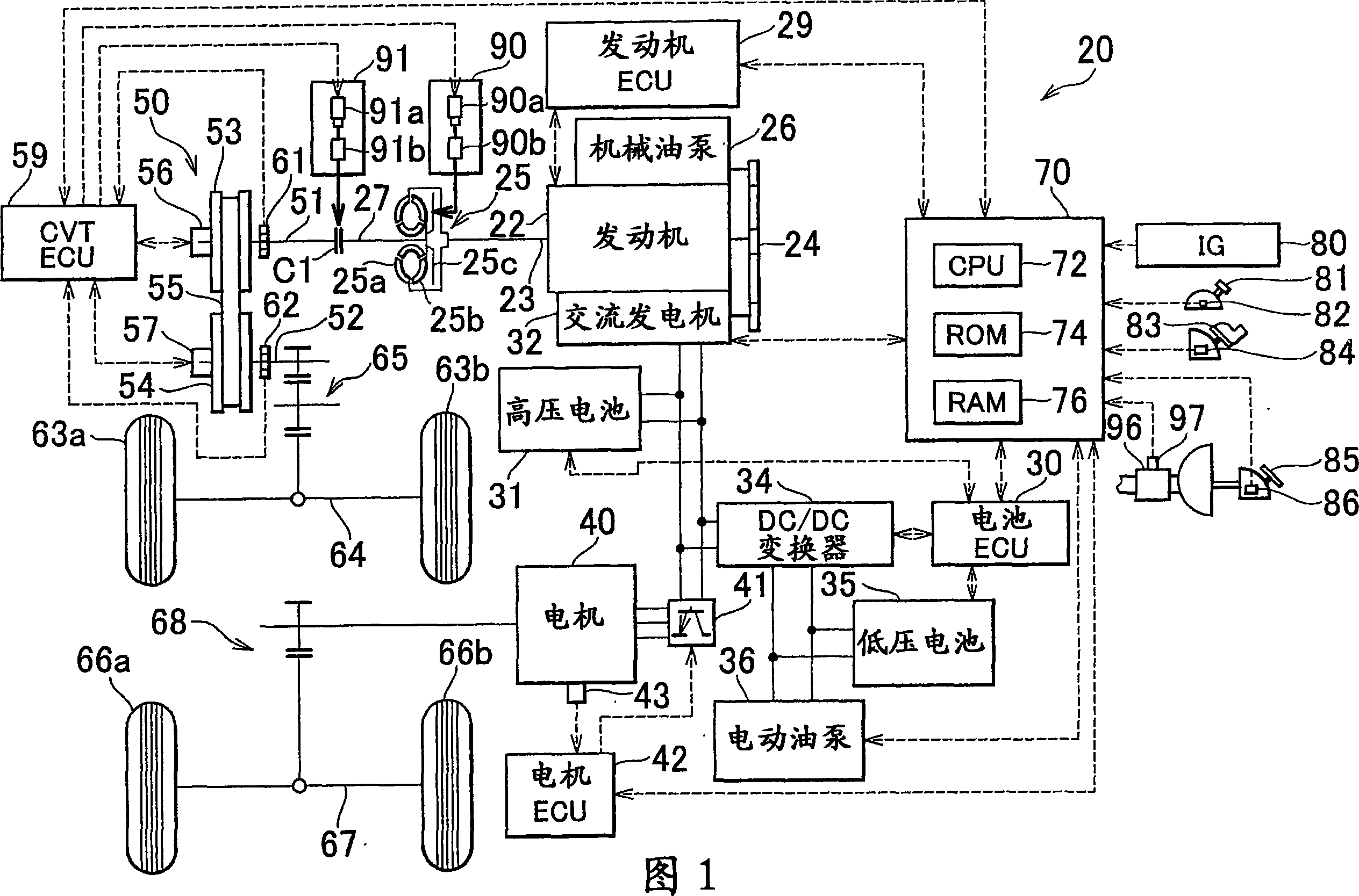
[0016] FIG. 1 shows the configuration of a hybrid vehicle 20 according to one embodiment of the present invention. The hybrid vehicle 20 according to this embodiment is a four-wheel drive vehicle capable of running by driving four wheels. The hybrid vehicle 20 includes a front-wheel drive system that drives the front wheels 63a and 63b by transmitting power from the engine 22 to the front axle 64 via the torque converter 25, the CVT 50, and the gear mechanism 65; Shaft 67 transmits power to drive rear wheels 66a and 66b; and a hybrid vehicle electronic control unit (hereinafter referred to as “hybrid ECU”) 70 controls the entire hybrid vehicle 20 . This hybrid vehicle 20 also includes a mechanical oil pump 26 that generates line pressure for the CVT 50, torque converter 25, and clutch C1 by using power from the engine 22; Electric oil pump 36 that generates line pre...


PUM


Abstract

Whether the master cylinder pressure Pm of the brake master cylinder is higher than the reference pressure Pmref is determined (step S 120). Based on the determination, the lock-up clutch of the torque converter is promptly released (step S130) or gradually released (step S140). Whether the master cylinder pressure Pm is higher than the reference pressure Pmref is determined (step S160). Based on the determination, the connection provided by the clutch is promptly terminated (step S170), or gradually terminated (step S180). Because the lock-up clutch is released and the connection provided by the clutch is terminated based on the operation of the brake pedal performed by the driver, a sense of discomfort felt by the driver can be suppressed.

Description

technical field [0001] The invention relates to a vehicle and a control method thereof. Background technique [0002] There is known a vehicle in which an engine and an electric motor are provided as driving power sources, the engine is connected to a torque converter including a lock-up clutch and a transmission via a first clutch, and the electric motor is connected to the torque converter via a second clutch (for example, refer to Japanese Patent Application Publication No. JP-A-2000-103259). In such a vehicle, after the lock-up clutch is disengaged, by disengaging one of the first clutch and the second clutch that has been engaged (apply), and engaging the other of the first clutch and the second clutch that has been disengaged, the The drive power source is switched between the engine and the electric motor. In this way, torque fluctuations due to such switching between the two driving power sources are absorbed by the torque converter, so that shock can be reduced. ...

Claims


Application Information

Patent Timeline
Patent Type & Authority Applications(China)
IPC IPC(8): B60W30/18B60W10/02B60W10/06B60W10/10B60K6/48B60K6/52B60K6/543B60L50/16B60W10/04B60W10/08B60W20/00F02D29/00F02D29/02F02D29/06F02D41/04F02D45/00F16H59/54F16H61/14
CPCB60W30/18Y10T477/639B60K2741/025B60W10/02B60W10/04B60W30/1819
Inventor 奥田弘一太田隆史永野周二
Owner TOYOTA JIDOSHA KK
Why Eureka
Try Eureka