Bandwidth-constrained signal regulation

A signal conditioning and signal technology, applied in impedance networks, digital technology networks, electrical components, etc., can solve problems such as increasing complexity and increasing costs

Inactive Publication Date: 2007-12-12
TELEFON AB LM ERICSSON (PUBL)
View PDF1 Cites 1 Cited by
  • Summary
  • Abstract
  • Description
  • Claims
  • Application Information

AI Technical Summary

Problems solved by technology

This increases the complexity of implementation, and therefore also costs

Method used


Image

  • Bandwidth-constrained signal regulation
  • Bandwidth-constrained signal regulation
  • Bandwidth-constrained signal regulation

Examples


Embodiment Construction

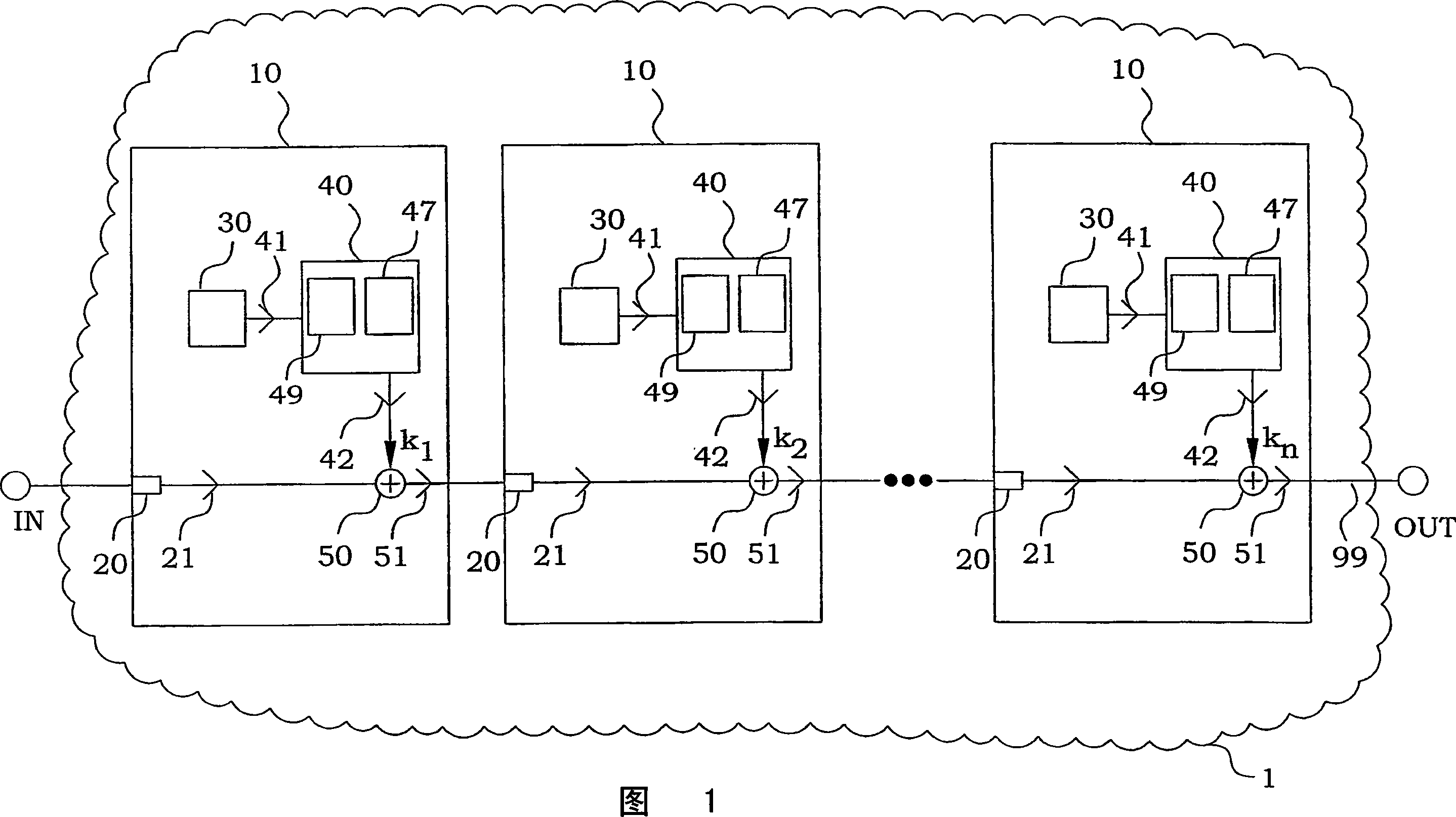
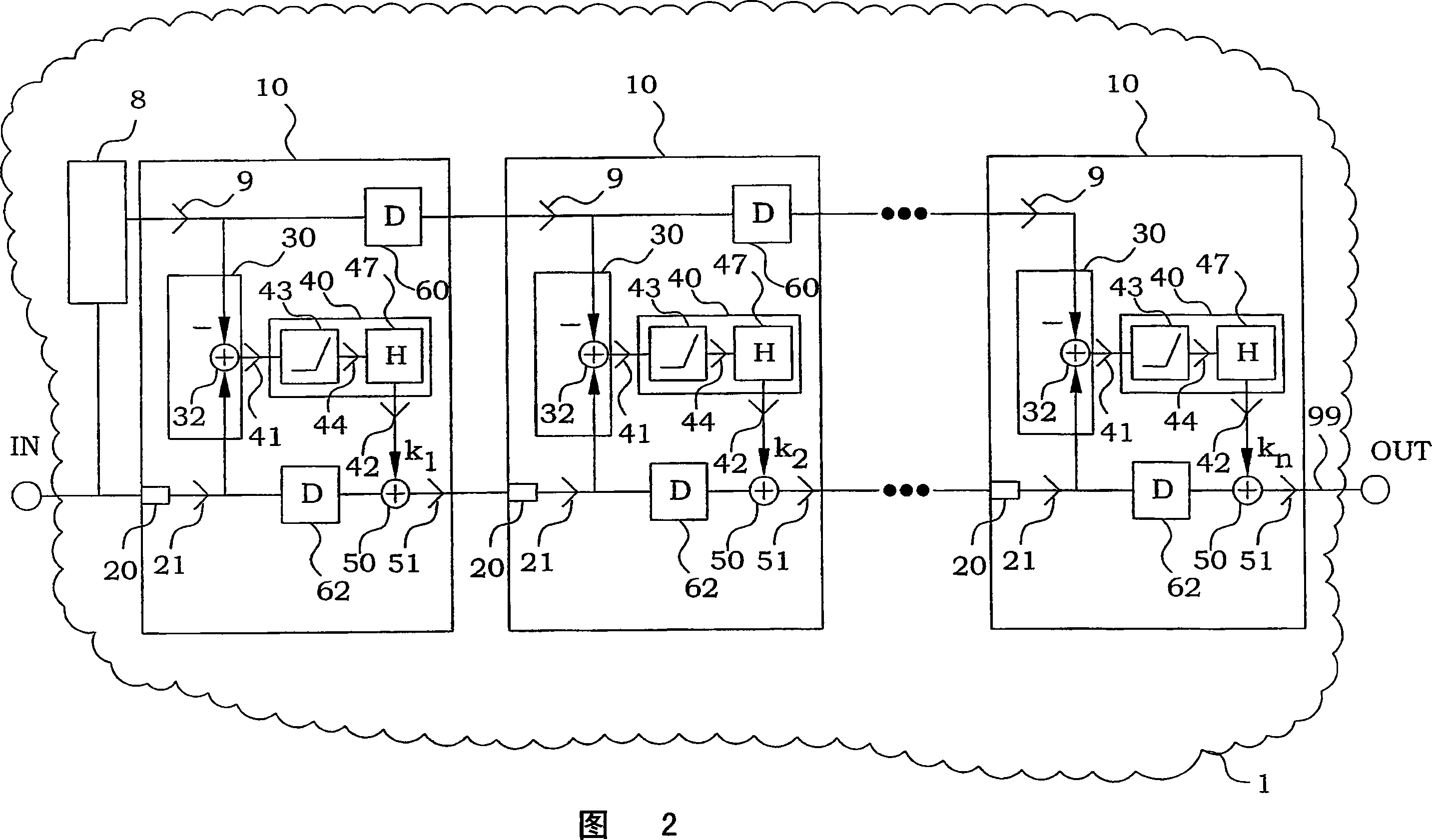
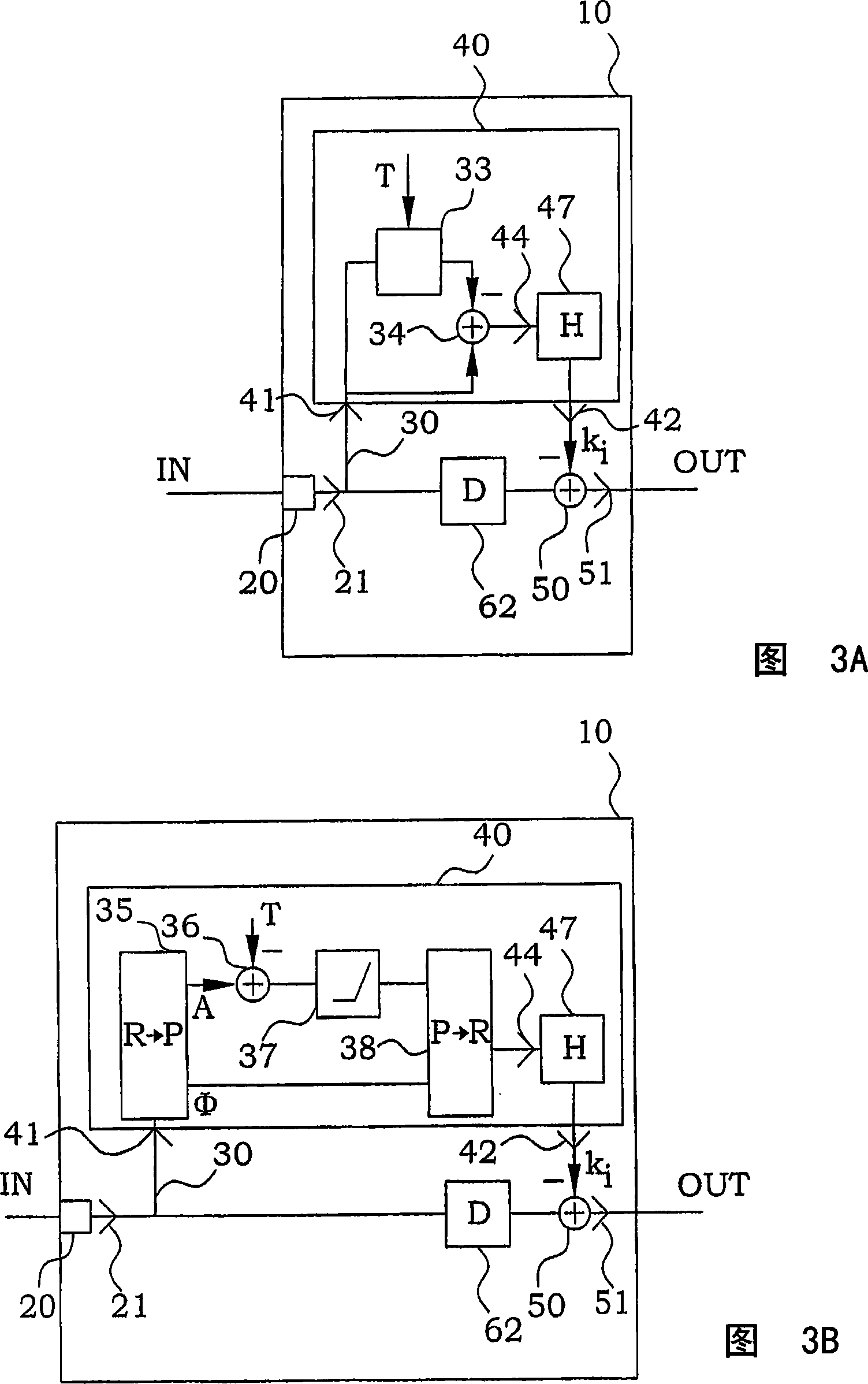
[0023] Good performance such as low PAR in peak reduction while meeting EVM and ACPR specifications generally requires more steps of signal non-linearity correction and subsequent filtering than is used in prior art solutions. If good performance is obtained by extending state-of-the-art solutions to more steps without further modification, more steps are required.

[0024] The present invention indicates an alternative path in which good performance is obtained by reinserting the non-linearly corrected signal by a reinsertion factor greater than unity. For at least one subsequent step and in a particular embodiment for each subsequent step, the reinsertion factor increases. The reinsertion factor may, for example, increase exponentially with the number of steps, increase linearly, or increase by some other scheme. Any reinsertion factor is not discussed in the prior art, ie it is always assumed to be equal to or close to 1. In a particular embodiment of the invention, the f...


PUM


Abstract

Non-linear signal conditioning is provided by signal processing in at least 2 consecutive steps (10). In each step (10) an insertion source signal (41) is provided, which is treated non-linearly to fulfill certain restrictions in bandwidth and / or spectral mask. The insertion signal is combined with a main signal (21) using a reinsertion factor (k1-kn), as a correction of the main signal (21). The reinsertion factor of at least one step is larger than the reinsertion factor of a previous step. In particular embodiments, the reinsertion factor increases for each of the at least 2 steps. This principle can be applied to most non-linear signal processing, and for example in PAR reduction systems, dynamic drain bias PA systems, Doherty and Chireix PA systems and in Dynamic Gate Bias systems.

Description

technical field [0001] The present invention generally relates to methods and apparatus for non-linear signal conditioning of alternating signals, and in particular to such apparatus and methods where the signal must remain within bandwidth and / or spectral constraints. Background technique [0002] In many applications, typically in various communication systems and especially in multi-carrier and multi-user systems, there is a need for nonlinear correction of signals. In many cases, this non-linear correction must be kept within a certain bandwidth or within a certain spectral mask restriction. A typical example of this nonlinear correction is peak-to-average ratio (PAR) reduction, also known as decresting or clipping. PAR reduction improves power amplifier (PA) efficiency and average output power. The aim is to reduce the peak amplitude excursion of the output signal while keeping the spectral spread within given limits, such as spectral masking and adjacent channel powe...

Claims


Application Information

Patent Timeline
Patent Type & Authority Applications(China)
IPC IPC(8): H03H17/06
CPCH03F2200/15H03H2218/12H03F1/3241H03H17/0261H03F1/0205H03F2200/435H03F2200/18H03F3/24H03F1/0288H03H17/06
Inventor R·赫尔伯格
Owner TELEFON AB LM ERICSSON (PUBL)
Why Eureka
Try Eureka