High performance magnetic pump

A magnetic pump, high-performance technology, used in pumps, pump components, components of pumping devices for elastic fluids, etc., can solve problems such as magnetic rotor overheating, burnt equipment, spindle bearing damage, etc.

Active Publication Date: 2007-12-19
DANDONG COLOSSUS GROUP
View PDF0 Cites 10 Cited by
  • Summary
  • Abstract
  • Description
  • Claims
  • Application Information

AI Technical Summary

Problems solved by technology

The magnetic pump is equipped with an isolation sleeve between the inner magnetic rotor and the outer magnetic rotor to form a sealed cavity, which seals the main shaft and the inner magnetic rotor in the sealed cavity. Cooling with the inner magnetic rotor part, the rotor cavity formed by the spacer sleeve is connected to the pump cavity, and the medium in the high pressure area in the pump cavity is used to cool the rotor cavity, and the devices in the sealed cavity formed by the spacer sleeve are completely Immersed in the conveyed medium, the corrosiveness of the medium and the sand and other impurities in the medi

Method used


Image

  • High performance magnetic pump
  • High performance magnetic pump

Examples


Embodiment Construction

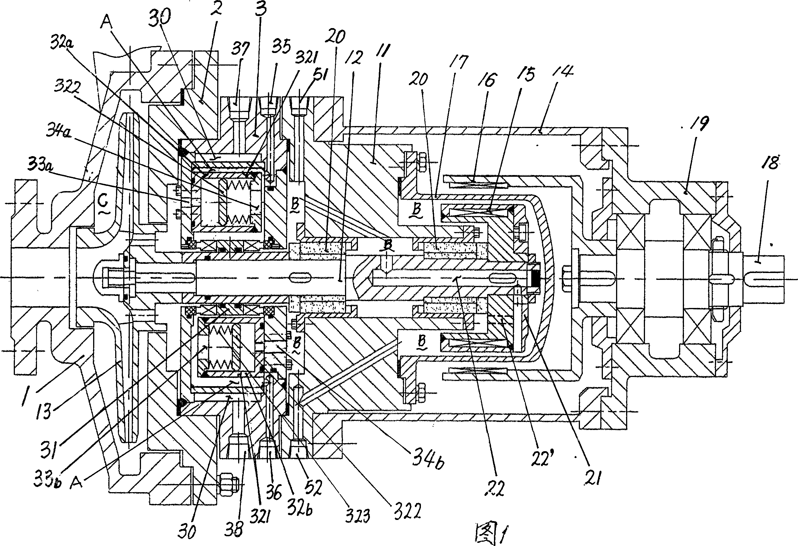
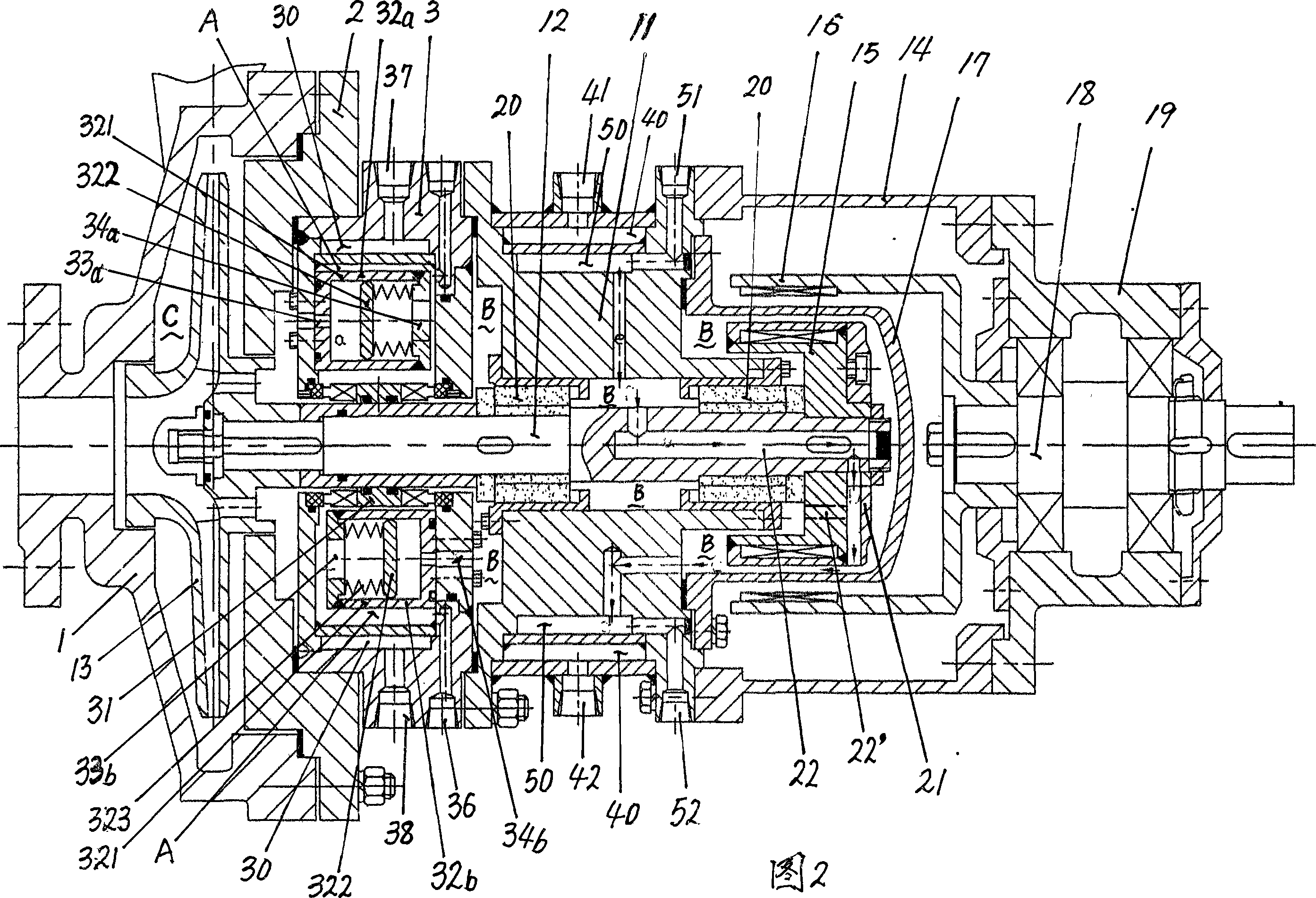
[0010] Referring to Figure 1, the present invention includes a pump body 1, a pump cover 11, a pump shaft 12, an impeller 13, a coupling frame 14, an inner magnetic rotor 15, an outer magnetic rotor 16, an isolation sleeve 17, a drive shaft 18, and a drive shaft The bearing box 19, the pump shaft 12 and the pump cover 11 are installed and connected through rolling bearings or sliding bearings 20, the coupling frame 14 is fixedly connected with the pump cover 11, the drive shaft bearing box 19 is docked and fixedly connected with the coupling frame 14, and the inner magnetic rotor 15 is fixed Installed on the shaft end of the pump shaft 12, the outer magnetic rotor 16 is fixedly installed on the shaft end of the drive shaft 18, and a spacer 17 is arranged between the inner magnetic rotor 15 and the outer magnetic rotor 16, and the spacer 17 is sealed and fixedly connected with the pump cover 11, Between the pump body 1 and the pump cover 11, a front pump cover 2 and a sealing bo...


PUM


Abstract

The present invention relates to a high-performance magnetic drive pump. Said high-performance magnetic drive pump includes the following several portions: pump body, pump cover, pump shaft, blade wheel, coupling frame, internal magnetic rotor, external magnetic rotor, isolation sleeve, drive shaft and drive shaft bearing. Said invention also provides its working principle and concrete method.

Description

technical field [0001] The present invention relates to a magnetic pump. Background technique [0002] The magnetic pump is a pump in which the outer magnetic rotor and the inner magnetic rotor cooperate to drive the inner magnetic rotor to rotate through magnetic force, and the inner magnetic rotor drives the pump shaft to rotate, so that the impeller rotor on the pump shaft in the pump body rotates to work. The magnetic pump is provided with an isolation sleeve between the inner magnetic rotor and the outer magnetic rotor to form a sealed cavity, which seals the main shaft and the inner magnetic rotor in the sealed cavity. Cooling with the inner magnetic rotor part, the rotor cavity formed by the spacer is connected to the pump cavity, and the medium in the high pressure area in the pump cavity is used to cool the rotor cavity, and the devices in the sealed cavity formed by the spacer are completely Immersed in the conveyed medium, the corrosiveness of the medium and the ...

Claims


Application Information

Patent Timeline
IPC IPC(8): F04D29/08F04D29/58
Inventor 马伟利王慧于华宇李岩
Owner DANDONG COLOSSUS GROUP
Why Eureka
Try Eureka