Source drive amplifier for flat panel display

A driving amplifier and source-driven technology, applied to static indicators, instruments, etc., can solve the problems of slow response, increased power consumption and circuit size of auxiliary buffers, and the inability of auxiliary buffers to have large driving capabilities, so as to maintain output Accuracy, the effect of high output accuracy

Active Publication Date: 2007-12-19
SOLOMON SYSTECH CHINA LTD
View PDF1 Cites 12 Cited by
  • Summary
  • Abstract
  • Description
  • Claims
  • Application Information

AI Technical Summary

Problems solved by technology

Addition of auxiliary buffer increases power consumption and circuit size
In order to minimize additional power consumption and to offset its effect on the main push-pull output during charging (see Figure 5(c)) and discharging (see Figure 5(d)), the auxiliary buffer cannot have a large drive capability
This results in a slow response during the |Vin-Vout| < Vos condition, as shown in the region close to V_high and V_low in Figure 6(b)

Method used


Image

  • Source drive amplifier for flat panel display
  • Source drive amplifier for flat panel display
  • Source drive amplifier for flat panel display

Examples


Embodiment Construction

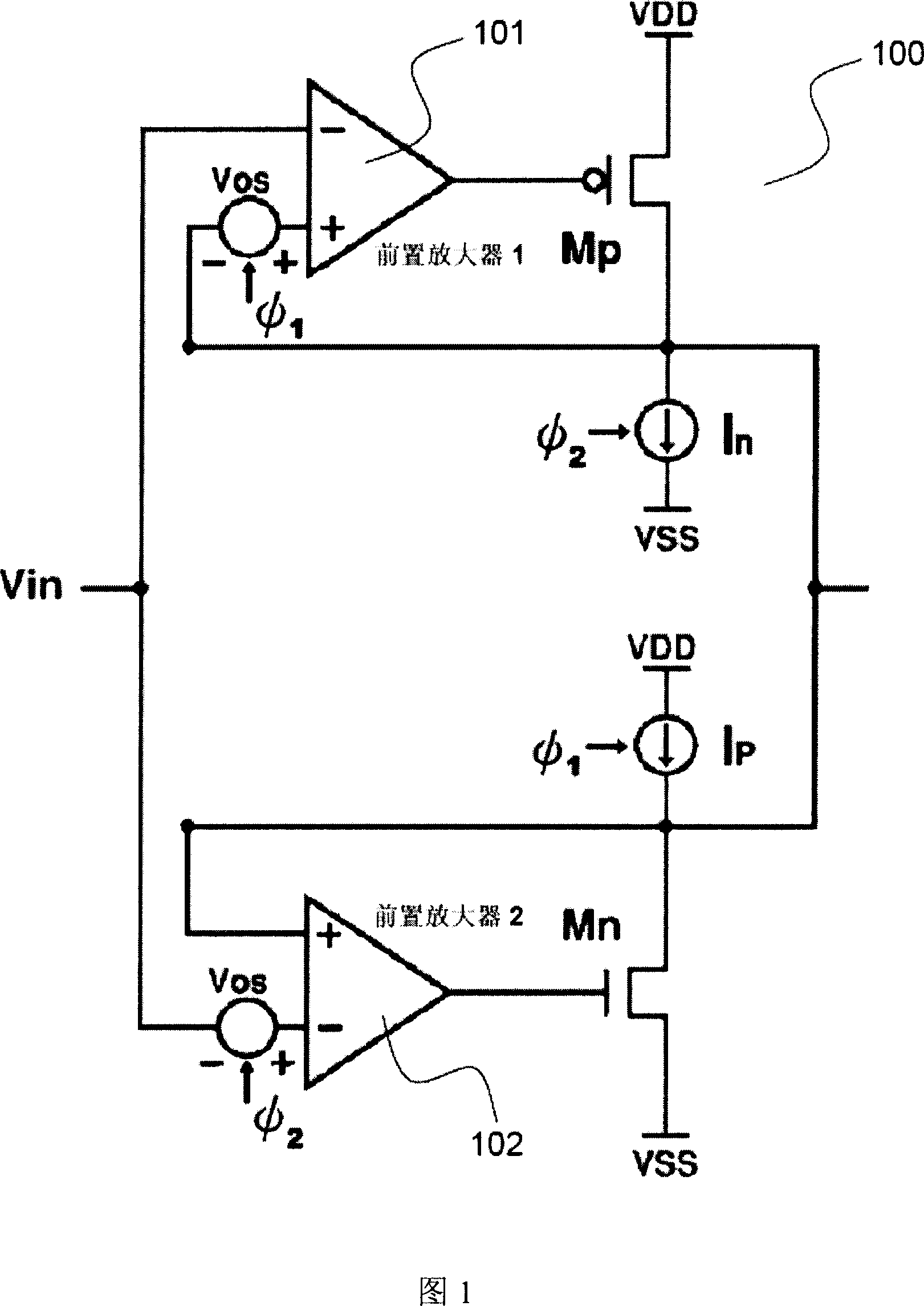
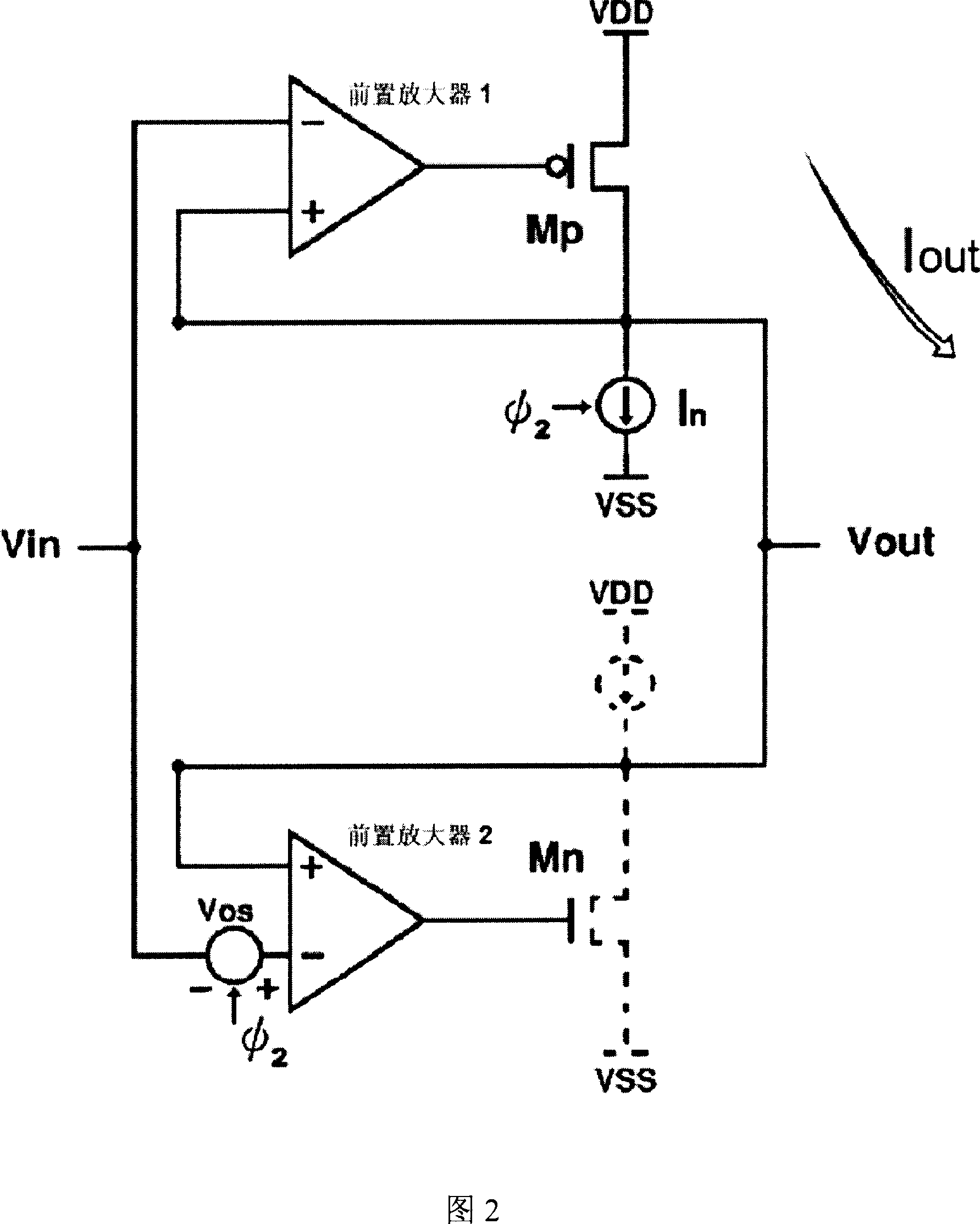
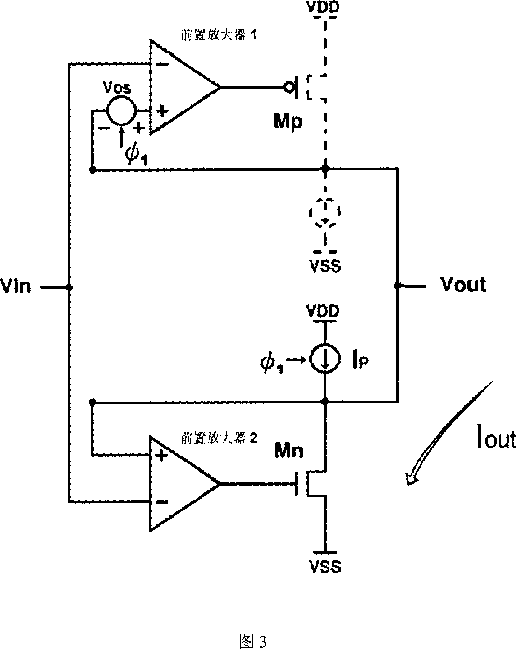
[0041] FIG. 1 shows a driver amplifier 100 according to the present disclosure and optimally configured for use in a source driver device for a TFT-LCD structure. The driver amplifier 100 includes a complementary push-pull output stage structure using a common source connection structure output transistors Mp and Mn, the drains of Mn and Mp are coupled to the output terminal Vout. This configuration allows bidirectional supply of current from the driver amplifier 100 to the load. Transistors Mp and Mn are each driven by a corresponding differential preamplifier 101 and 102, respectively. Both Mp and Mn can be realized by PMOS or NMOS. A switchable voltage offset Vos is provided to each preamplifier 101 and 102 . The offset voltage of each preamplifier can be connected to either the non-inverting input or the inverting input of the preamplifier.

[0042] In the implementation of Figure 1, Mn is an NMOS transistor and Mp is a PMOS transistor. The preamplifier 101 is used to ...


PUM


Abstract

An output buffer (100) for a TFT-LCD display device comprising a push-pull output stage having a first device (Mp) for supplying current to an output terminal (Vout) and a device for slave A second device (Mn) that draws current at its output. A first preamplifier (101) is coupled to an input (Vin) of a buffer for driving a first device to provide current to an output. A second preamplifier (102), coupled to the input for driving a second device drawing current from the output; the first switchable offset is related to the first preamplifier (101) and the second switchable offset The quantity is related to the second preamplifier (102). A switchable current source (Ip) is used to supply current to the output and a switchable current sink (In) is used to draw current from the output. The switching input φ1 is used to activate the first switchable offset and switchable current source and the complementary switching input φ2 is used to activate the second switchable offset and switchable current sink.

Description

technical field [0001] The present invention relates to a source driving amplifier of a flat panel display, in particular to a source driving amplifier used in a driving circuit of a thin film transistor liquid crystal display. Background technique [0002] Thin film transistor liquid crystal display (TFT-LCD) is considered to be the dominant array type display. The array consists of a plurality of pixels (or dots), each pixel having a drive electrode and a common electrode shared with other pixels. The LCD is driven by an AC (alternating current, alternating current) signal. In such a structure, if the voltage applied to the drive electrodes is positive with respect to the voltage applied to the common electrode when the first frame is displayed, then the voltage applied to the common electrode in the next successive frame is positive The voltage to the drive electrodes is negative. The voltage applied to the drive electrodes is provided by column drivers (also known as ...

Claims


Application Information

Patent Timeline
Patent Type & Authority Applications(China)
IPC IPC(8): G09G3/36G09G3/20G02F1/133
CPCG09G3/20G09G2310/0291G09G3/3614G09G3/3685G09G2310/0275
Inventor 李长辉李耀生
Owner SOLOMON SYSTECH CHINA LTD
Why Eureka
Try Eureka