High reliable de-excitation method for generater

A technology for generators and generator rotors, applied in electrical components, emergency protection circuit devices, etc., can solve the problem of inability to achieve demagnetization, and achieve the effect of demagnetization time and high safety demagnetization.

Inactive Publication Date: 2007-12-19
STATE GRID ELECTRIC POWER RES INST +1
View PDF0 Cites 8 Cited by
  • Summary
  • Abstract
  • Description
  • Claims
  • Application Information

AI Technical Summary

Problems solved by technology

The main problem of this type of de-excitation method is that when the AC side voltage is low (such as a short circuit at the machine terminal) or the closed thyristor pulse fails, it will not be able to achieve de-excitation
[0009] Aiming at the problem that large-capacity units have higher req

Method used


Image

  • High reliable de-excitation method for generater
  • High reliable de-excitation method for generater

Examples


Embodiment Construction

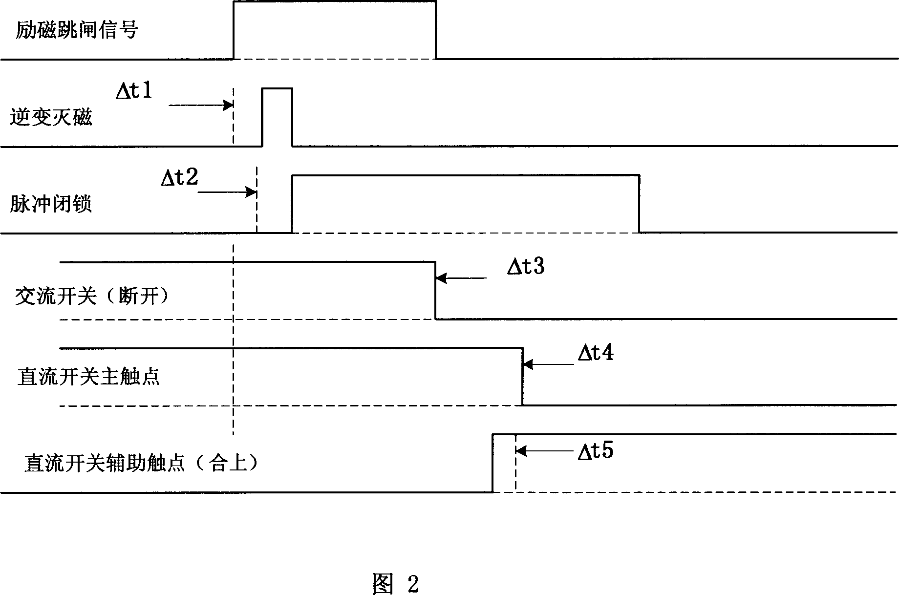
[0024] As shown in Figure 2, when the generating set stops in an accident (taking 50 Hz as an example), the trip order is sent to the excitation regulator to control the inverter at the same time (the inverter is delayed by about 6-7ms compared to the trip order), After the inverter de-excitation of 2 control cycles, the de-excitation is controlled according to the de-excitation timing method of the present invention. In the figure, Δt1 is the time from the regulator receiving the inverter order to the start of the inverter; Δt2 is the time from the start of the inverter to the pulse blockade. Time, Δt3 is the action time of the AC de-excitation switch, Δt4 is the action time of the main break of the DC switch, and Δt5 is the action time of the normally closed auxiliary break of the DC switch before the main break. Typical time values ​​are as follows: Δt1 is 6 to 7 milliseconds, Δt2 is 6 to 7 milliseconds, Δt3 is 60 milliseconds, Δt4 is 60 to 80 milliseconds, and Δt5 is 1 to 2...


PUM


Abstract

This invention relates to a stable demagnetization method, which controls de-magnet according to the time sequence at the state when a generator is faulty: 1, at the time when an excitation regulator gets an excitation trip order from a set protection device, it starts up inversion de-magnet, 2, sending the trip order to an AC de-magnet switch and a DC de-magnet switch, 3, the excitation regulator executes the inversion to set a pulse control angle an inversion angle after delta-t1, 4, closing down the output pulse of the regulator with software or hardware after inverting for delta-t2, in which, delta-t1 is in the sphere greater than 0ms but smaller than or equal to 10ms, and delta-t2 is in the sphere greater than 4ms and smaller than or equal to 10ms, and the demagnetization methods of DC, AC, inverted and non-linear resistor energy-moving and closing pulse of thyristor are used inter-grate to realize stable demagnetization.

Description

Technical field [0001] The invention relates to a highly reliable generator de-excitation method with de-excitation protection function for the generator excitation system, belonging to the technical field of generator excitation circuit control. Background technique [0002] When the generator internal fault or overvoltage occurs, in order to minimize the impact of the accident, the demagnetization system is required to transfer the electromagnetic energy of the generator rotor at the fastest speed, so that the generator voltage drops to zero quickly. In recent years, with the increasing capacity of generator sets, the generator rotor demagnetization has also realized the transformation from energy consumption type to energy transfer type, and from linear demagnetization to nonlinear demagnetization. [0003] At present, the excitation method generally adopts self-parallel excitation. The electrical principle of the main circuit of the general excitation system is shown in ...

Claims


Application Information

Patent Timeline
IPC IPC(8): H02H7/06
Inventor 朱晓东许其品刘国华
Owner STATE GRID ELECTRIC POWER RES INST
Why Eureka
Try Eureka