Stabilizer bush

A stabilizer and bushing technology, applied in spring/shock absorbers, multi-purpose hand tools, interconnection systems, etc., can solve problems such as increased friction, easy deformation, easy intrusion of soil, sand, dust, and muddy water, etc., to prevent Longitudinal bending deformation, the effect of suppressing the deformation of the contact surface, and ensuring the tightening margin

Inactive Publication Date: 2007-12-19
HONDA MOTOR CO LTD
View PDF0 Cites 12 Cited by
  • Summary
  • Abstract
  • Description
  • Claims
  • Application Information

AI Technical Summary

Problems solved by technology

[0012] However, if the tightening margin is increased, the frictional force during the rotational movement of the stabilizer increases, and there is a problem that the operating safety and ride comfort of the automobile are reduced, so it is not possible to increase the tightening margin.
[0013] In addition, in the stabilizer bushing having the slit 130 shown in FIG. 10, only the portion where the slit is formed is easily deformed. Therefore, a space S is formed between the shaft hole 110 and the stabilizer 200, and there are dirt, dust, muddy water, etc. The problem of easy intrusion into the gap

Method used


Image

  • Stabilizer bush
  • Stabilizer bush
  • Stabilizer bush

Examples


Embodiment Construction

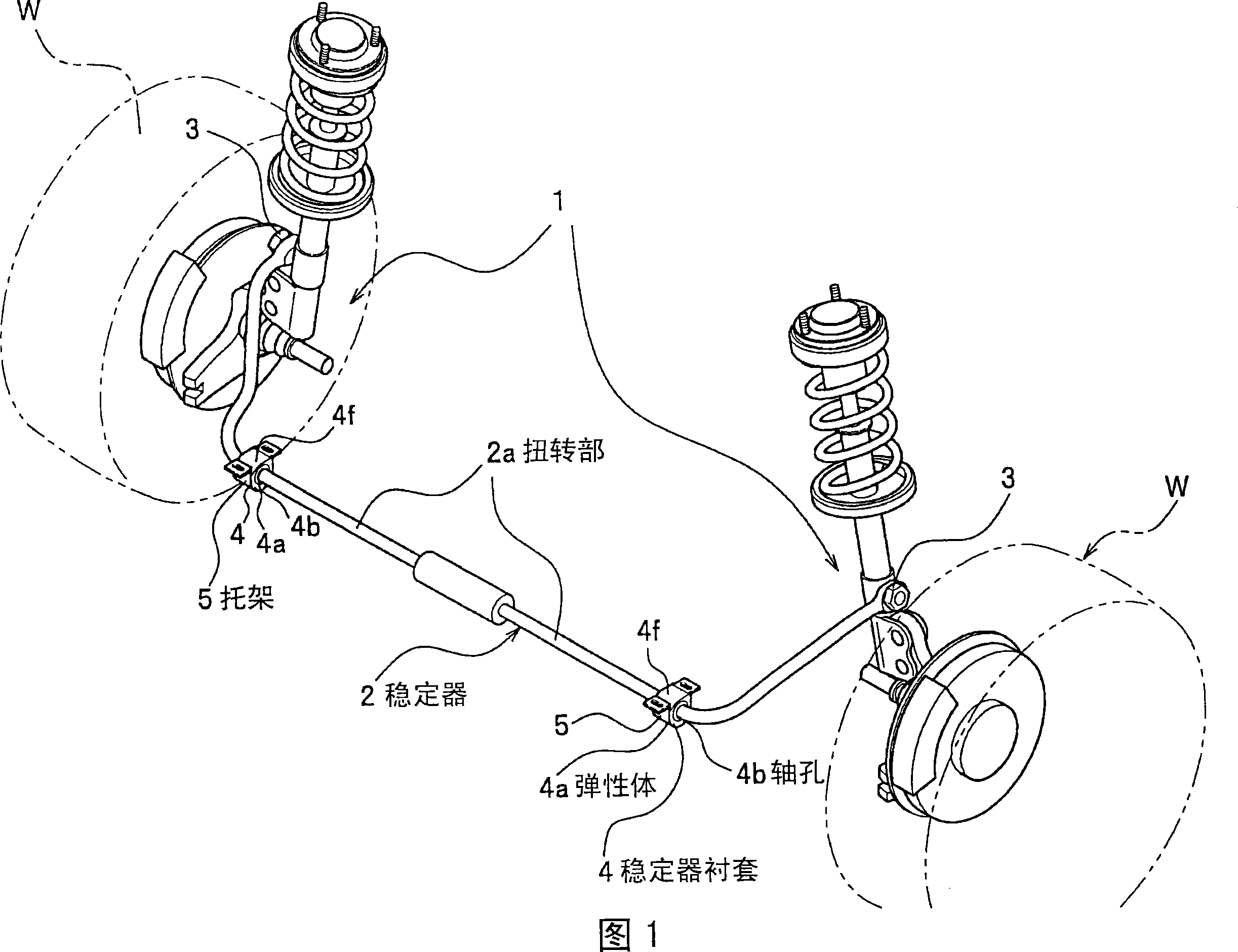
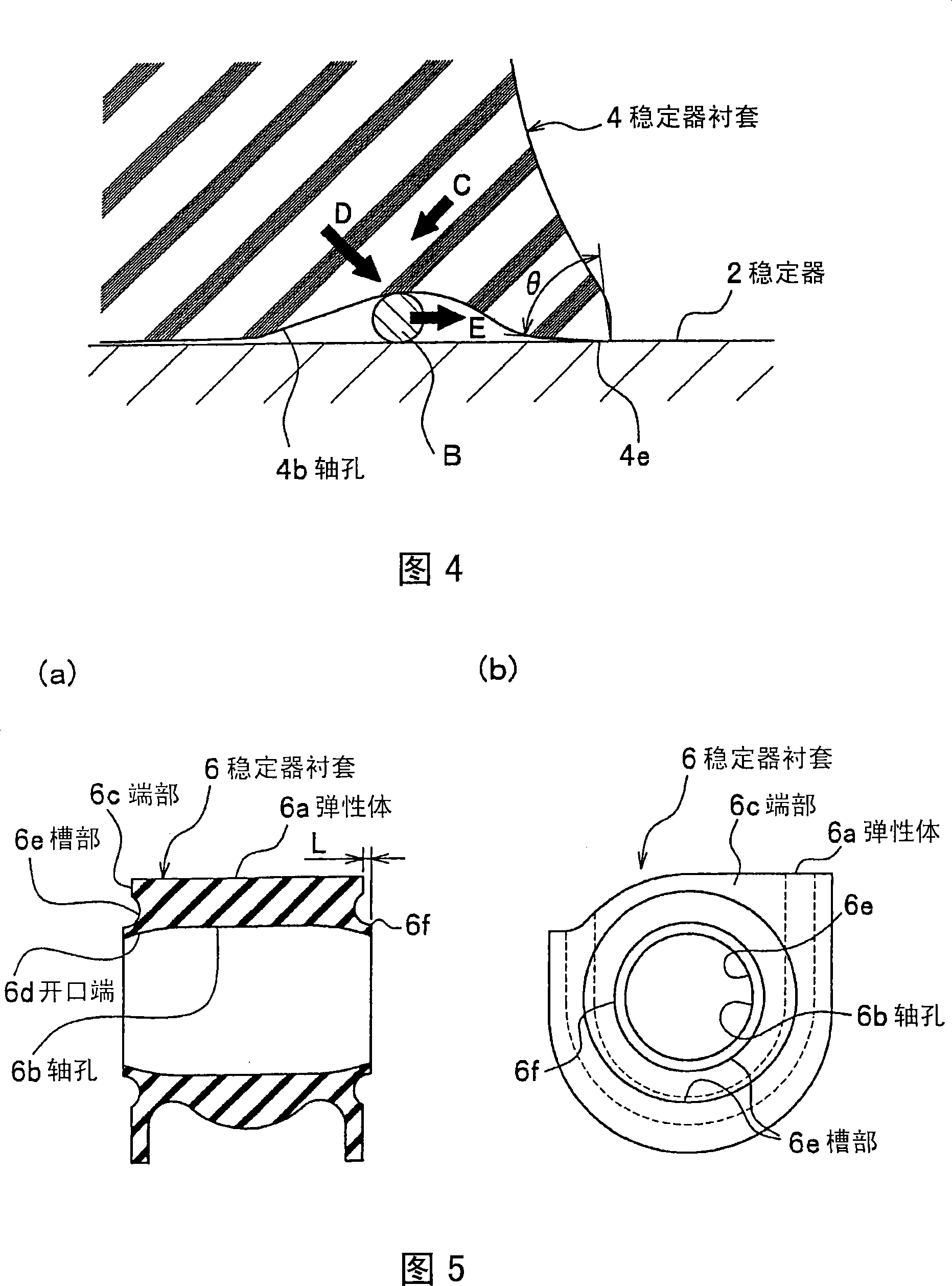
[0054] Hereinafter, the stabilizer bushing according to the embodiment of the present invention will be described with reference to FIGS. 1 to 4. Fig. 1 is a perspective view of a stabilizer showing an installed state of a stabilizer bushing according to an embodiment of the present invention.

[0055] "The composition of the stabilizer"

[0056] As shown in FIG. 1, the stabilizer 2 is a device that suppresses the lateral sway of the vehicle body when the vehicle is turning, and is mounted on the independent suspension 1 of the vehicle body so that the left and right wheels W individually rotate. The stabilizer 2 includes a torsion portion 2a made of a bar-shaped spring member, and bolt insertion holes (not shown) for fastening by bolts 3 are formed at the left and right ends, respectively. Stabilizer bushes 4 are fitted in the middle of the left and right sides of the stabilizer 2.

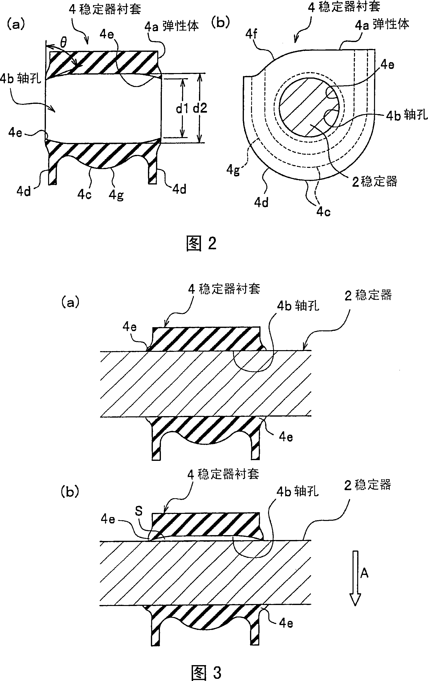
[0057] "Constitution of stabilizer bushing"

[0058] As shown in Fig. 1, the stabilizer bushing 4 p...


PUM


Abstract

A stabilizer bush (4) in which the torsion part (2a) of a stabilizer (2) is inserted and held in a shaft hole (4b) formed in an elastic body (4a) and the outer peripheral surface (4c) of the elastic body (4a) is held by a bracket (5) installed on a vehicle body. The shaft hole (4b) is so formed that its inner diameters (d1, d2) are gradually reduced from the axial center position to the outside.

Description

Technical field [0001] The present invention relates to a stabilizer bushing that holds the torsion part of a vehicle stabilizer (also called a stabilizer bar). Background technique [0002] The torsion portion of a conventional vehicle stabilizer is inserted into a stabilizer bush for vibration prevention made of a rubber elastic body formed in a substantially cylindrical shape, and is mounted to the vehicle body through a bracket. [0003] Such a stabilizer is attached to the vehicle body via a stabilizer bushing, thereby damping vibrations and collisions of the vehicle body. In addition, as in the stabilizer bushing of Patent Document 1, flanges that are in close contact with the stabilizer are respectively formed at the left and right open ends of the shaft hole. This flange prevents soil, sand, dust, cement, etc. from intruding into the sliding contact surface of the stabilizer bushing and the stabilizer in the shaft hole. [0004] Fig. 10 is an enlarged cross-sectional view...

Claims


Application Information

Patent Timeline
Patent Type & Authority Applications(China)
IPC IPC(8): B60G21/055F16F1/36F16F15/08
CPCF16F1/3835B60G2204/1222F16F1/3732B60G21/0551Y10T16/05B60G2204/41
Inventor 宫本康生铃木和贵山崎裕二
Owner HONDA MOTOR CO LTD
Why Eureka
Try Eureka