Irrigation and drainage pipes

A technology of an outer pipe and an inner pipe, applied in the field of drainage and irrigation pipe devices, can solve the problems of blocking the water outlet of the drainage pipe, blocking the pipe, reducing the drainage area of ​​the pipe, etc.

Inactive Publication Date: 2007-12-26
土谷神生活科技有限公司
View PDF0 Cites 8 Cited by
  • Summary
  • Abstract
  • Description
  • Claims
  • Application Information

AI Technical Summary

Problems solved by technology

It is easy to block the drainage hole, and the drainage effect of the main drainage channel is extremely poor during drainage; moreover, when the water passes through the drainage hole or filter cloth, most of the sand and mud components will be driven and attached, and it will accumulate over time. It will block the hydrophobic orifice passing through the pipe wall or the pores of the filter cloth, and the drainage effect will no longer be produced. However, if the diameter of the hydrophobic orifice on the pipe wall is enlarged, the compressive strength of the pipe body of the drain pipe will be reduced, resulting in The pipe body is broken, and when large-scale sand and mud enter the pipe through the enlarged hydrophobic orifice, it will accumulate at the bottom of the pipe, reducing the drainage area of ​​the pipe, and even causing blockage of the pipe
Moreover, when the irrigation and drainage pipe is used on a slope, there will be plants taking root at the water outlet position of the existing drainage pipe, and when the plant grows up, it will block the water outlet of the drainage pipe.
This kind of blockage caused by plants taking root on the ground is mainly due to the fact that there is a large amount of sand and mud at the water outlet of the drainage pipe, which is alluvial and aggregated at the bottom of the pipe. If it is alluvial to the water outlet of the pipe, it will be It will become a hotbed for plants to germinate and grow. When the plants grow luxuriantly, they will block the outlet of the pipe; it may also be because the drain pipes in use are evenly opened on the circumference of the pipe wall. Therefore, the seeds of plants can extend their young roots into the gaps in the drainage holes at the bottom of the drainage pipe even in the water outlet position where there is little accumulation of sand and mud, and take root in the drainage holes near the bottom. After lush growth, it will block the water outlet of the pipe

Method used


Image

  • Irrigation and drainage pipes
  • Irrigation and drainage pipes
  • Irrigation and drainage pipes

Examples


Embodiment Construction

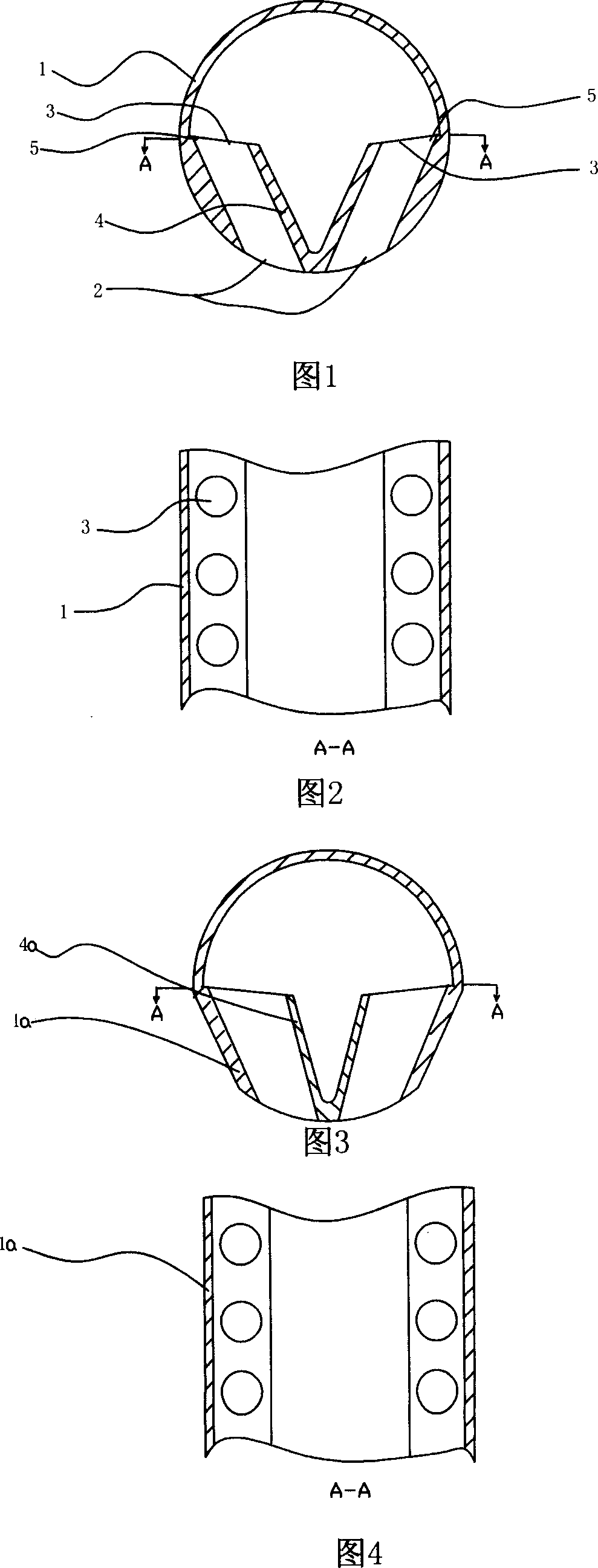
[0035] Below in conjunction with accompanying drawing, the utility model is further described.

[0036] As shown in Figures 1 and 2, the first embodiment of the irrigation and drainage pipe includes a circular outer pipe 1 and a number of drainage and irrigation holes 2 on the outer wall at the bottom of the outer pipe, and a main waterway is also arranged in the outer pipe. The main water channel is a water tank 4, and a number of inner wall irrigation and drainage holes 3 are arranged on the wall of the water tank higher than the position of the bottom drainage and irrigation holes. on the ear pieces. The cross-section of the outer pipe is circular, the height of the water tank is about 1 / 2 of the height of the pipe body, and the cross-section of the water tank is horseshoe-shaped.

[0037] Compared with the existing technology, when using it, the water source is first passed through the mixed fertilizer field material system to become the irrigation water mixed with the fe...


PUM


Abstract

The present invention discloses a drainage and irrigation pipe. It includes external pipe and several external wall drainage and irrigation holes which are cut on the external pipe wall; in the pipe interior of said external pipe also a main water channel is set; on the wall of said main water channel, in the position higher than external wall drainage and irrigation holes several internal wall drainage and irrigation holes are set. Compared with existent technique, in the process of use of said drainage and irrigation pipe lots of sand-mud granules can not be fed into the drainage and irrigation interior.

Description

technical field [0001] The invention relates to an irrigation and drainage pipe device used in a drip irrigation system, in particular to an irrigation and drainage pipe provided with drainage and irrigation holes at different horizontal positions. Background technique [0002] Existing irrigation and drainage pipes are drained in such a way that water passes through the hydrophobic holes distributed on the pipe wall or the pores of the filter cloth, enters the drain pipe, and then discharges out of the pipe through the main drain channel. It is easy to block the drainage hole, and the drainage effect of the main drainage channel is extremely poor during drainage; moreover, when the water passes through the drainage hole or filter cloth, most of the sand and mud components will be driven and attached, and it will accumulate over time. It will block the hydrophobic orifice passing through the pipe wall or the pores of the filter cloth, and the drainage effect will no longer b...

Claims


Application Information

Patent Timeline
Patent Type & Authority Applications(China)
IPC IPC(8): A01G25/00
CPCA01G25/06
Inventor 梁耀德
Owner 土谷神生活科技有限公司
Why Eureka
Try Eureka