
Boosting oil cylinder

An oil cylinder and force-increasing technology, which is applied in the field of hydraulic devices, can solve the problems of increasing the structural size of the piston and the oil cylinder, difficulty in transportation and construction, and leakage of seals, and achieves the effect of avoiding the increase in the size of the oil cylinder.

Inactive Publication Date: 2007-12-26
韩顺和 +1
View PDF0 Cites 13 Cited by
  • Summary
  • Abstract
  • Description
  • Claims
  • Application Information

AI Technical Summary

Problems solved by technology

[0003] The problem with this structure is that the thrust output by the hydraulic cylinder is limited by the pressure of the hydraulic system. For example, under the premise of a certain hydraulic system pressure, in order to increase the thrust output by the hydraulic cylinder, the working area of ​​the piston must be increased, that is, the piston must be increased. diameter, thereby increasing the structural size of the piston and cylinder, resulting in increased manufacturing costs, inconvenient use, and difficulties in transportation and construction; High oil pumps also lead to increased production costs. In addition, due to the use of high-pressure pumps, the pressure of the hydraulic system increases, causing the existing seals of the hydraulic cylinders to easily leak, so higher requirements are placed on the sealing structure.

Method used


Image

  • Boosting oil cylinder
  • Boosting oil cylinder

Examples


Embodiment Construction

[0022] The present invention will be described in detail below with reference to specific examples.

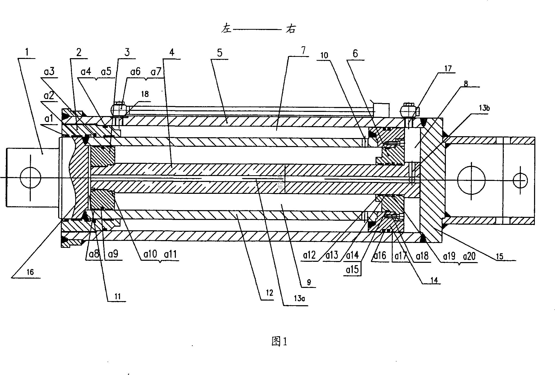
[0023] As shown in Figure 1, Figure 1 is a longitudinal sectional view of the booster cylinder of the present invention. The booster oil cylinder comprises a cylindrical cylinder body 5, the cylinder body 5 has two ends opposite to each other in the axial direction, one end is closed by the cylinder head 15 by being welded into one with the cylinder head 5, and the other end is provided with a large body fixed therewith. The guide sleeve 2, the outer surface of the large guide sleeve 2 and the inner surface of the cylinder body 5 are sealed by an O-ring back-up ring a4 and an O-ring seal a5.

[0024] A large piston rod 1 that is substantially coaxial with the cylinder body 5 is provided. The large piston rod 1 includes a large piston rod main body 12 and a connecting portion 16. The large piston rod main body 12 is cylindrical with a cylindrical cavity inside. A cylindrical s...


PUM


Abstract

This invention discloses a force cylinder including a cylinder, first stage piston components 14, 1 moving to-and-fro and second stage piston components 3, 4 moving to-and-fro relatively to the first stage piston components, in which the first components include a first master oil cavity and a second master oil cavity, the second components include a first sub-cavity and a second sub-cavity connected with the two master cavities separately, rod 4 of the second components passes through piston 14 of the first, the first master cavity is connected with the first sub-cavity via an oil transportation channel set in the first piston components, the second master cavity is connected with the second sub-cavity via an oil transportation channel set in the second piston components.

Description

technical field [0001] The invention relates to a hydraulic device, in particular to a device for linear reciprocating movement of components pushed by fluid pressure. Background technique [0002] The structure of the hydraulic cylinder commonly used in the prior art is as follows: including a cylinder body, a reciprocating piston assembly is arranged in the cylinder body, including a piston rod and a piston fixedly installed on the piston rod, and the piston separates the cylinder body into front , the two rear chambers, when oil enters the rear chamber and oil exits the front chamber, the piston is pushed forward, thereby pushing the piston rod forward to output thrust; when the front chamber enters oil and the rear chamber exits oil, push The piston moves backward, thereby pushing the piston rod back into the rigid body. [0003] The problem with this structure is that the thrust output by the hydraulic cylinder is limited by the pressure of the hydraulic system. For ex...

Claims


Application Information

Patent Timeline
IPC IPC(8): F15B15/17
Inventor 韩顺和张晓玲
Owner 韩顺和
Learn More