Hydraulic disk type integrated arrestor with adjustable braking force

A hydraulic brake and braking force technology, applied in the direction of hydraulic brakes, brake types, brake components, etc., can solve the problems of high price, hidden danger of brake failure, cumbersome friction plate replacement procedures, etc., to achieve convenient replacement and maintenance, accurate estimated effect

Inactive Publication Date: 2007-12-26
SANY HEAVY IND CO LTD (CN)
View PDF0 Cites 24 Cited by
  • Summary
  • Abstract
  • Description
  • Claims
  • Application Information

AI Technical Summary

Problems solved by technology

The existing disc hydraulic brakes have the following problems. One is that the components are complex in structure and expensive; Braking, the wear rate of the friction plate is high, and it

Method used


Image

  • Hydraulic disk type integrated arrestor with adjustable braking force
  • Hydraulic disk type integrated arrestor with adjustable braking force

Examples


Example Embodiment

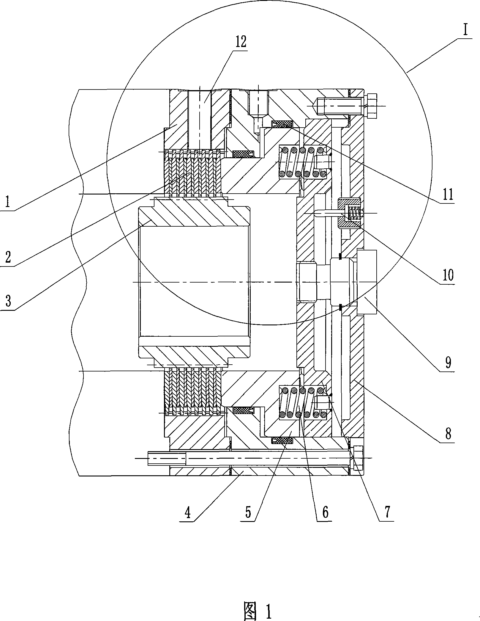
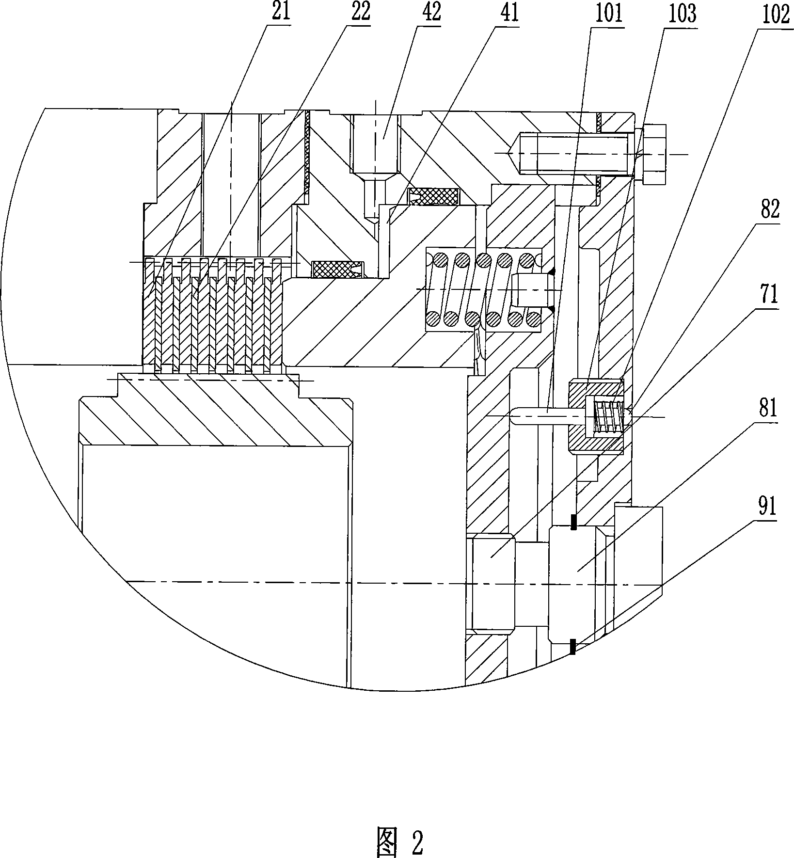
[0025] As shown in Figures 1 and 2, the disc hydraulic brake with adjustable braking force of the present invention includes a working device and a power device. The working device is composed of a connecting external gear 3, an internal gear ring 1 and a friction plate set 2, which are connected The shaft outer gear 3 is located in the inner gear ring 1, and the friction plate set 2 is arranged between the connecting shaft outer gear 3 and the inner gear ring 1. The power unit consists of the housing 4, the piston 5, the compression spring 6, the baffle 7 and the seal 11. The piston 5 and the baffle 7 are sleeved in the housing 4, one end of the piston 5 is connected to the friction plate group 2, and the other end is connected to the baffle 7 through the compression spring 6, and the seal 11 is provided on the outer wall of the piston 5 and the housing Between the inner walls of 4, the housing 4 and the inner gear ring 1 are connected by fasteners. The present invention also inc...


PUM


Abstract

This invention discloses a disk hydraulic brake with brake force adjustable including a working device composed of an internal gear loop and friction wafers and a dynamic device composed of a shell, a piston, a compression spring, a baffle and a sealing piece, in which a connection outer gear is set in the internal gear loop, the friction wafer set is set between the outer gear and the internal gear loop, the piston and the baffle are set in the outer shell, one end of the piston is connected with the friction wafer set, the other end is connected with the baffle by the compression spring, the sealing piece is set between the outer wall of the piston and the inside wall of the shell, which is connected with the internal gear loop by a fastener. This invention also includes a regulation device composed of an end cover, a test device and regulation bolts, and the cover is connected with the baffle by the bolt and a test device testing the space between the cover and the baffle is set on the end cover connected to the shell.

Description

technical field [0001] The invention relates to the field of hydraulic brakes, in particular to disc hydraulic brakes with adjustable braking force. Background technique [0002] At present, disc hydraulic brakes that can provide large braking torque, reliable braking, and stability have been increasingly used in large construction machinery and industrial equipment. Its main working parts include: dynamic friction plate, static friction plate, hydraulic components, springs, etc. The principle is to use the interaction between the spring force and the hydraulic pressure to realize the normally closed and normally open states. The existing disc hydraulic brakes have the following problems. One is that the components are complex in structure and expensive; For braking, the wear rate of the friction plate is high, and it is difficult to detect the friction plate, and it is difficult to judge the amount of wear; the fourth is that the braking force cannot be adjusted, and ther...

Claims


Application Information

Patent Timeline
IPC IPC(8): F16D55/40F16D65/20F16D65/18
Inventor 张寒李翠英蒋殿珍
Owner SANY HEAVY IND CO LTD (CN)
Why Eureka
Try Eureka