
Angle rotatable camera

A technology of rotation angle and camera, which is applied in the field of cameras, can solve the problems of reduced monitoring efficiency, spherical camera lens guidance, monitoring dead angle, etc., and achieve the effect of improving monitoring efficiency

Inactive Publication Date: 2011-02-02
COMPAL ELECTRONICS INC
View PDF0 Cites 0 Cited by
  • Summary
  • Abstract
  • Description
  • Claims
  • Application Information

AI Technical Summary

Problems solved by technology

[0003] However, the disadvantage of this dome camera is that two motors are used to control the left to right movement and the upward and downward movement of the photographic lens respectively. lead to desired fixed point
Therefore, when the dome camera rotates the camera lens to scan the surrounding environment during monitoring, because the camera lens cannot move quickly and accurately to the fixed point of monitoring, there will be a gap in the monitoring time, so there will be a monitoring dead angle and monitoring efficiency will decrease

Method used


Image

  • Angle rotatable camera
  • Angle rotatable camera
  • Angle rotatable camera

Examples


Embodiment Construction

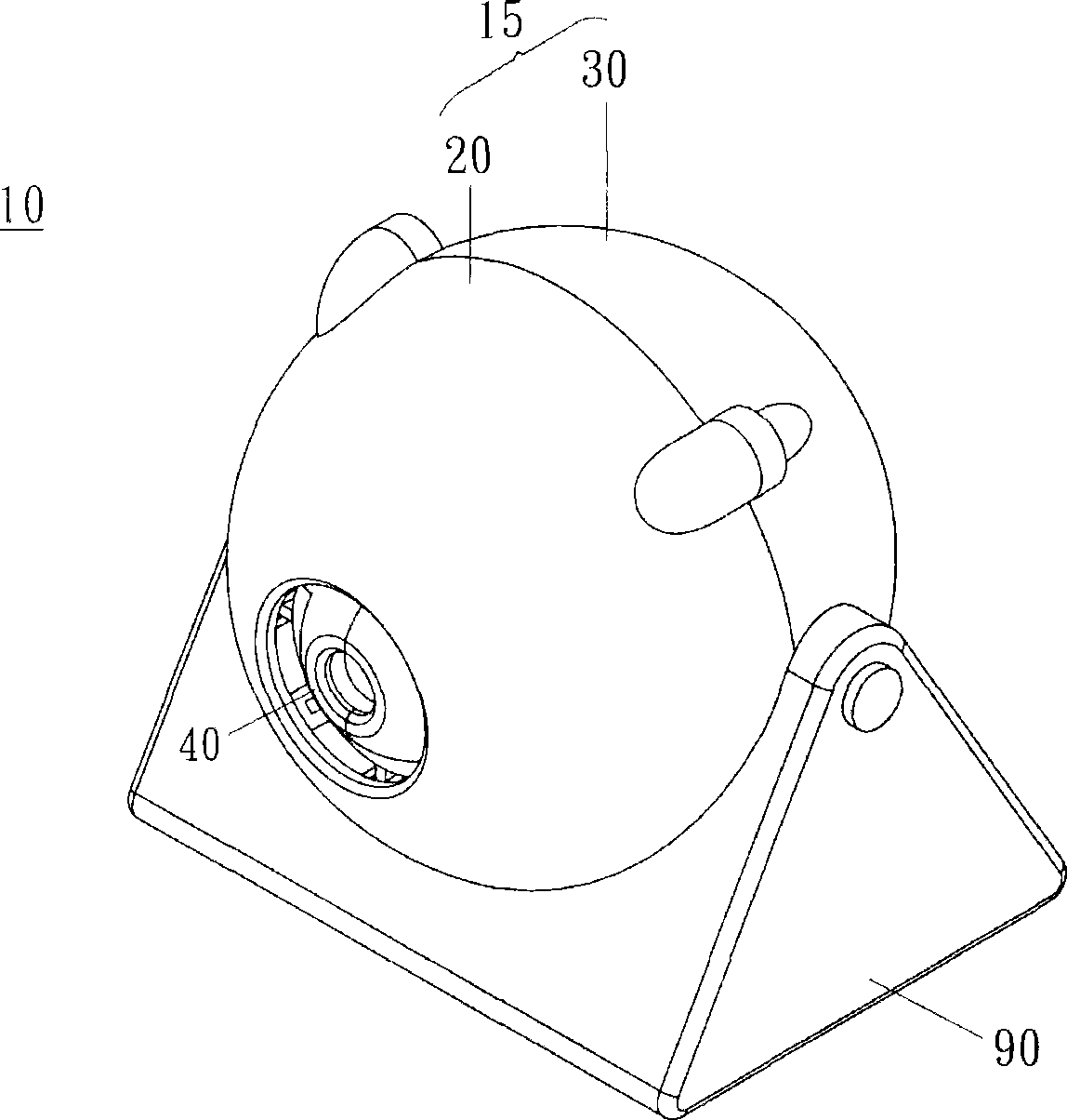
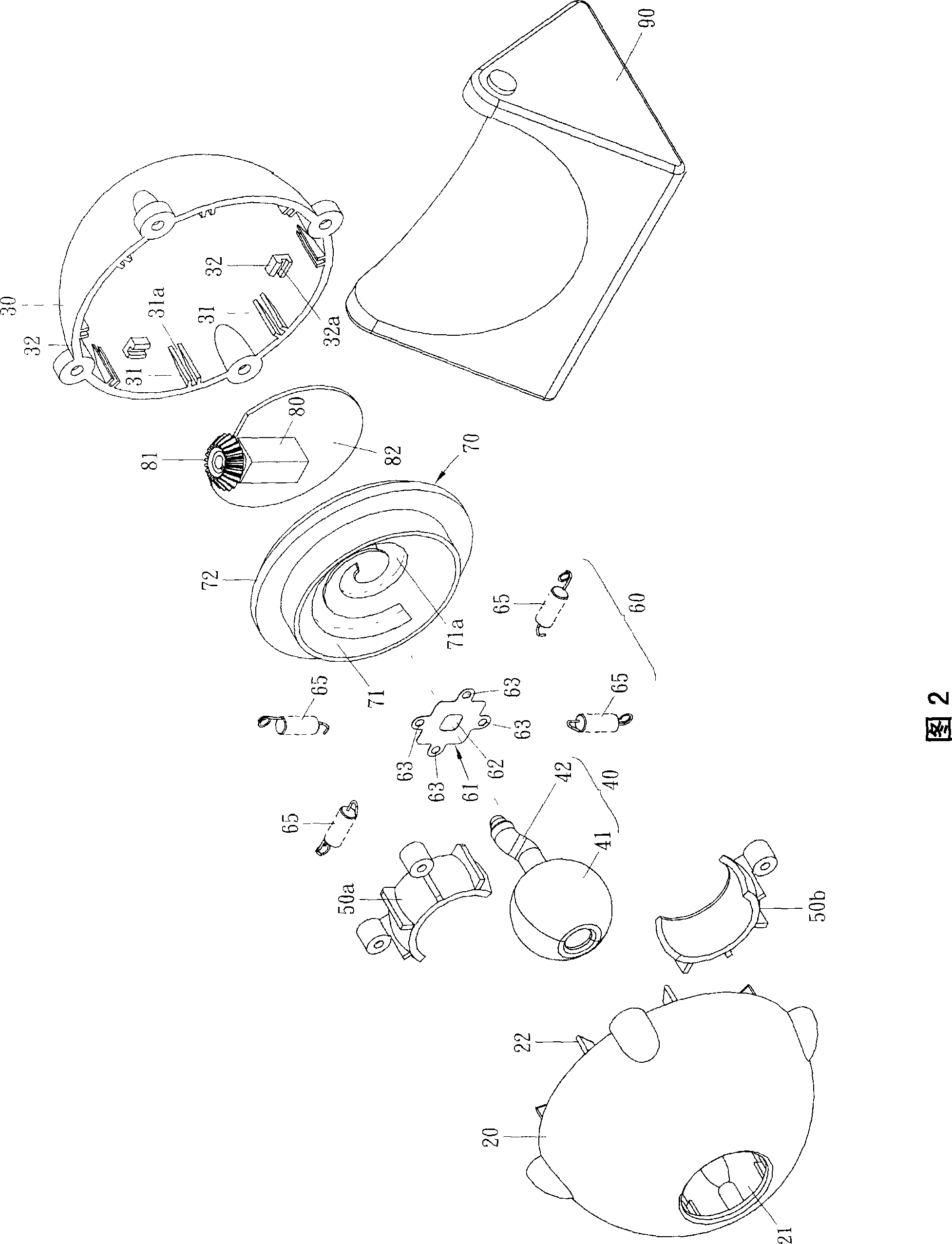
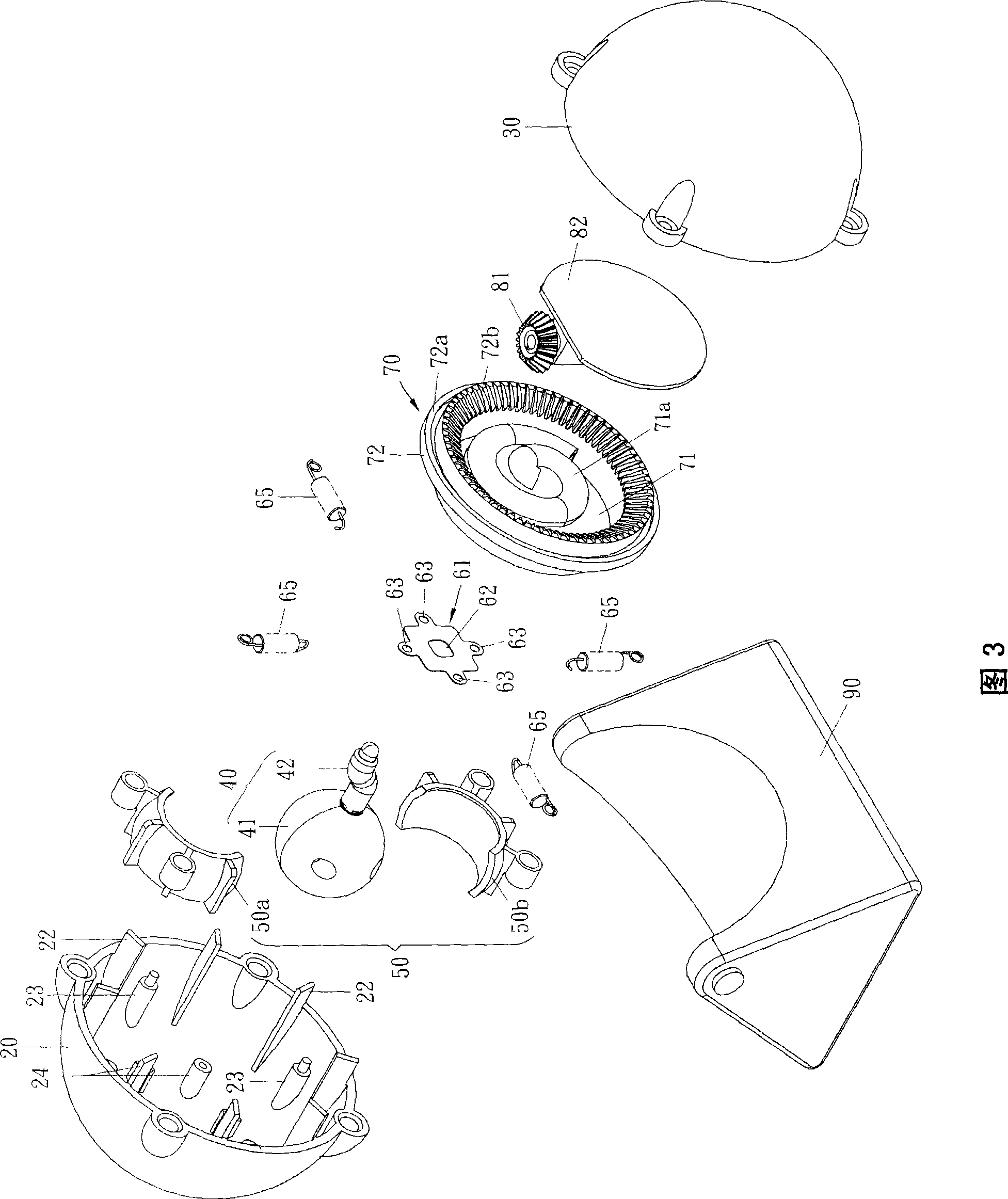
[0030] Such as Figure 1 to Figure 4 As shown, the camera 10 shown in the present invention is composed of a casing 15, a base 90 pivotally arranged below the casing 15, and a lens unit 40 pivotally arranged inside the casing 15.

[0031] Wherein, the casing 15 is composed of a front casing 20 and a rear casing 30, and the inside of the casing 15 is provided with a spherical bearing seat 50 and a suspension buffer mechanism 60 in addition to accommodating the lens unit 40. , a rotating disk 70 and a motor 80. Moreover, when the motor 80 is activated, the power of the motor 80 can drive the rotating disk 70 to rotate, and then the rotating disk 70 can drive the lens unit 40 to rotate and swing.

[0032] The front housing 20 is a hemispherical component with a notch 21 and a plurality of positioning wings 22 , fixing posts 23 and ribs 24 inside. Wherein, the positioning flap 22 is used to form a connection with the positioning groove 31 provided on the rear housing 30, and fac...


PUM


Abstract

A video camera with angle being able to be rotated is prepared for pin-jointing base under shell; setting lens unit with a shooting head and a guide rod, spherical bearing base, rotary disc with an arc-guide disc having spiral track, and motor in shell; carrying out spiral-trace swinging by guide rod of lens unit along spiral track at arc-guide disc on rotary disc for making said shooting head onlens unit immediately generate variation of rotary angle when rotary disc is driven by motor to rotate.

Description

technical field [0001] The invention relates to a camera with a rotatable angle, in particular to a dome camera which uses a single motor to change the rotation angle of a photographing lens. Background technique [0002] The dome camera in the prior art usually uses two motors in order to make the photographic lens move in all directions (360°) to track the object and take images, and one of the motors controls the photographic lens to move left and right (pan ) to move, and the other motor is used to control the tilting of the camera lens vertically in the left and right directions (tilt), so that the camera lens can move in both left and right and up and down directions. [0003] However, the disadvantage of this dome camera is that two motors are used to control the left to right movement and the upward and downward movement of the photographic lens respectively. Guide to desired fixed point. Therefore, when the dome camera rotates the camera lens to scan the surroundi...

Claims


Application Information

Patent Timeline
Patent Type & Authority Patents(China)
IPC IPC(8): G03B17/00G03B29/00G03B17/56
Inventor 龚绍祖林伯安陈永蕙
Owner COMPAL ELECTRONICS INC
Learn More