
Ink jet printing

An inkjet module and ink nozzle technology are applied in inkjet printing. field, to achieve the effect of improving reliability

Active Publication Date: 2010-04-14
FUJIFILM DIMATIX
View PDF10 Cites 0 Cited by
  • Summary
  • Abstract
  • Description
  • Claims
  • Application Information

AI Technical Summary

Problems solved by technology

Each ink nozzle includes a piezoelectric transducer

Method used


Image

  • Ink jet printing
  • Ink jet printing
  • Ink jet printing

Examples


Embodiment Construction

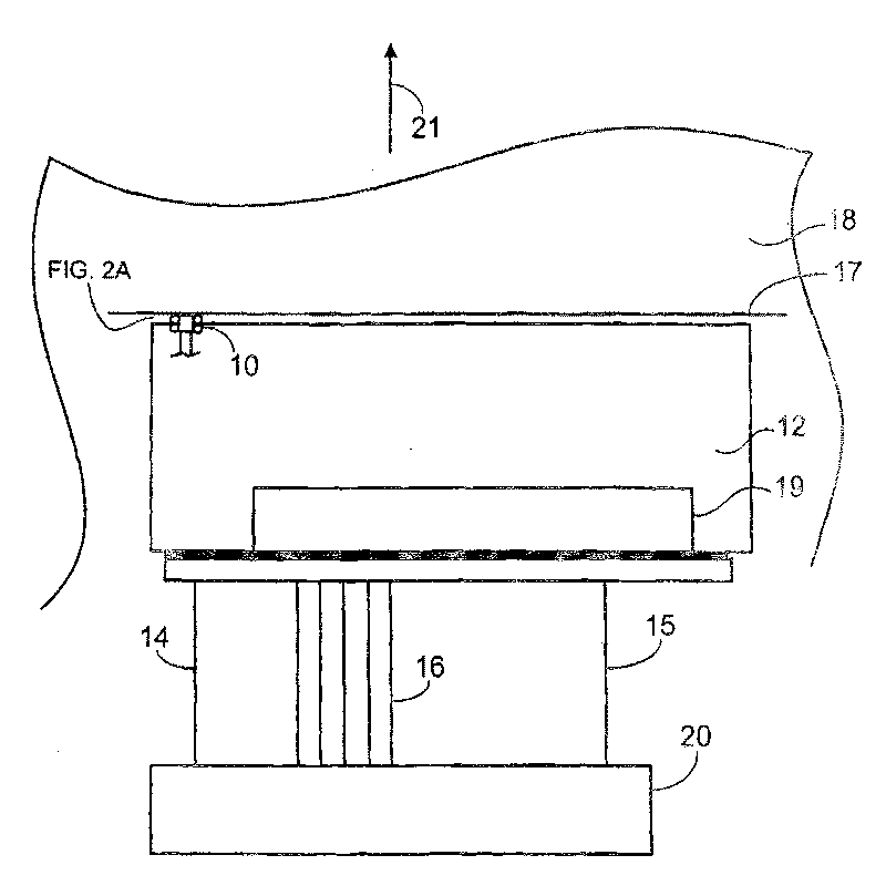
[0036] Refer to attached figure 1 , the inkjet module 12 includes a plurality (eg, 16, 64, 128, 256, 512 or more) of ink nozzles 10 driven by electrical drive pulses (in the attached figure 1 Only one is shown in ), the electrical drive pulses are provided on signal lines 14 and 15 and distributed by an on-board control circuit 19 in order to control the firing of the ink nozzles 10 . External controller 20 provides drive pulses on lines 14 and 15 and control data and logic power and timing to onboard control circuitry 19 on additional line 16 . Ink ejected by ink nozzles 10 may be delivered to form one or more print lines 17 on substrate 18 moving relative to inkjet module 12 (eg, in the direction indicated by arrow 21 ). In some embodiments, the substrate 18 moves past the stationary head module 12 in a single-pass mode. Optionally, inkjet module 12 may also be moved across substrate 18 in a scanning manner.

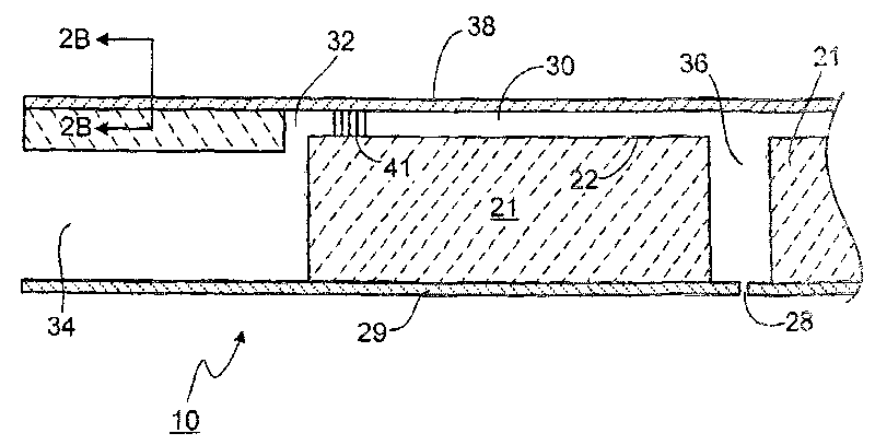
[0037] Refer to attached Figure 2A(Illustrating vertical sec...


PUM


Abstract

In general, in one aspect, the invention features a method of driving an inkjet module having a plurality of ink jets. The method includes applying a voltage waveform to the inkjet module, the voltagewaveform including a first pulse and a second pulse, activating one or more of the ink jets contemporaneously to applying the first pulse, wherein each activated ink jet ejects a fluid droplet in response to the first pulse, and activating all of the ink jets contemporaneously to applying the second pulse without ejecting a droplet.

Description

technical field [0001] The present invention relates to inkjet printing. Background technique [0002] An inkjet printer is a device that uses a droplet ejection device. In one type of inkjet printer, ink is delivered from a plurality of linear inkjet printhead arrangements oriented perpendicular to the direction of travel of the printed substrate. Each printhead assembly includes a plurality of integrally formed droplet ejection devices that define a plurality of plenum chambers (one for each individual droplet ejection device) on an upper surface, and has a piezoelectric actuator covering each plenum chamber. actuator. Each individual droplet ejection device is activated by a voltage pulse of the piezoelectric actuator to distort the shape of the piezoelectric actuator and eject a droplet synchronously with the substrate passing the printhead assembly at a desired time. [0003] Each individual droplet ejection device can be addressed independently, and can be activated...

Claims


Application Information

Patent Timeline
Patent Type & Authority Patents(China)
IPC IPC(8): B41J29/38B41J2/045
CPCB41J2/04596B41J2/04588B41J2/04581B41J2002/14403B41J2/04598B41J2/045B41J29/38
Inventor 保罗·A·霍伊辛顿迪恩·A·加德纳
Owner FUJIFILM DIMATIX
Learn More