A falling film heat exchanger with spiral arrangement of pipes

A falling film heat exchanger technology, applied in evaporators/condensers, lighting and heating equipment, refrigeration components, etc., can solve the problem of low space utilization of heat exchangers, heat exchange time of shell-side fluid and tube-side fluid Short and other problems, to achieve the effect of improving flexibility, reducing possibility, and high heat transfer density

Active Publication Date: 2015-10-21
ZHEJIANG UNIV
View PDF8 Cites 0 Cited by
  • Summary
  • Abstract
  • Description
  • Claims
  • Application Information

AI Technical Summary

Problems solved by technology

The heat transfer coefficient of the horizontal falling film evaporator is high, but the space utilization rate inside the heat exchanger is low; while the vertical falling film evaporator has a low space utilization rate, but the heat exchange time of the shell side fluid and the tube side fluid too short
Both heat exchangers use a distribution strategy only for the flow of the fluid of interest, but not for the other fluid

Method used


Image

  • A falling film heat exchanger with spiral arrangement of pipes
  • A falling film heat exchanger with spiral arrangement of pipes
  • A falling film heat exchanger with spiral arrangement of pipes

Examples


Embodiment 1

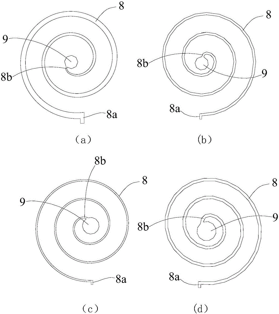
[0043] like Figure 7 , 8 , 9 This example is suitable for evaporators in the field of refrigeration and air conditioning, fluid A is selected as the refrigerant, and fluid B (air) is selected as the secondary refrigerant. Fluid A is in a gas-liquid mixed state before entering the heat exchanger. After entering the heat exchanger from the fluid A inlet 2 at the top, the fluid A passes through the fluid A distributor 7 and evenly sprays to the outer wall of the spiral pipe 8. The outer wall surface of the spiral pipe 8 flows downward in a film shape, because the temperature of the refrigerant A (fluid A and refrigerant A refer to the same substance in this embodiment 1) is lower than that of the refrigerant B (the fluid B and the refrigerant A in this embodiment 1 Refrigerant B refers to the same substance), so the heat is transferred from the brine to the refrigerant, and the temperature of the brine decreases. The generated refrigerant vapor is led out from the gaseous flui...

Embodiment 2

[0049] This example is suitable for the concentration and purification of substances in the chemical and pharmaceutical fields. Set fluid A as the liquid to be concentrated. At this time, the concentration of a certain substance a in fluid A is relatively low, and the channel of fluid B is passed through a hot fluid with a higher temperature (high temperature steam). The heat exchange process between the two is similar to that in Example 1. After successively passing through each layer of heat exchange pipes, the moisture in fluid A will be partially vaporized due to the heat obtained. As the heat exchange progresses, the concentration of substance a in fluid A increases, and the moisture or liquid impurities become less. Therefore, a fluid A containing a higher concentration of a is produced at the bottom of the heat exchanger, and when the required requirements are met, the heat exchanger can be separated from the bottom.

[0050] There is another variant of this embodiment...

Embodiment 3

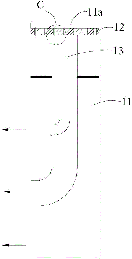
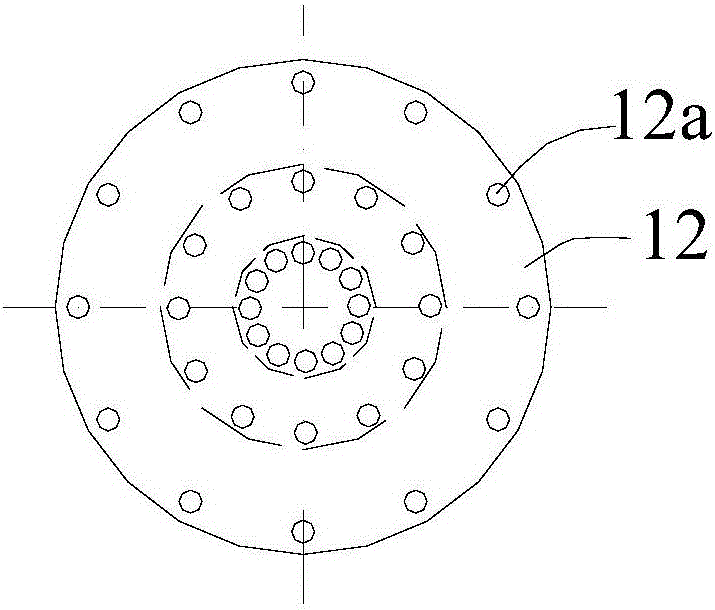
[0058] like figure 2 and image 3 Another implementation form of the present invention includes a fluid B distribution chamber 11, a fluid inlet 11a is provided on the fluid B distribution chamber 11, a fluid B distributor 12 is arranged in the fluid B distribution chamber 11, and a A fluid B distribution conduit 13 between the fluid B distributor 12 and the fluid B inlet 5 . There are two fluid B distribution pipes 13, the inlet ends of multiple fluid B distribution pipes 13 are nested with each other, and the outlet ends of the inner fluid B distribution pipes are connected to the fluid B inlets through the outer fluid B distribution pipes.

[0059] This embodiment is suitable for the heat exchange between two liquid working fluids and the required heat transfer is very small. Since the heat transfer is very small, it is assumed that the number of layers of spiral pipes in the main body of the evaporator is small ( This embodiment takes 3 layers as an example), the workin...


PUM


Abstract

The invention discloses a falling film type heat exchanger with tubes in spiral arrangement. The falling film type heat exchanger is characterized in that heat exchange tubes are in horizontal and spiral arrangement, and shell-side working media flow down along the outer wall surfaces of the tubes in a film-shaped manner. The falling type heat exchanger specifically comprises a shell, a fluid A inlet, a gaseous fluid A outlet, a liquid fluid A outlet, a fluid B inlet and a fluid B outlet are formed in the shell, a fluid A distributor is arranged in the shell, and at least one layer of spiral tubes and a collection tube communicated with outlets of the spiral tubes are further arranged in the shell; fluid inlets of the spiral tubes are all communicated with the fluid B inlet; a spiral form of the tubes is one of an Archimedes spiral form, a line segment evolvent form, a regular polygon evolvent form, a circle evolvent form and an ellipse evolvent form. Tube-side fluid inlet modes can be a direct fluid inlet method, a tube-in-tube fluid inlet method and a hose type fluid inlet method. The novel falling film type heat exchanger greatly widens working situations and application fields of conventional falling film type heat exchangers, and has good market application prospect.

Description

technical field [0001] The invention belongs to the technical field of falling-film heat exchanger design, in particular to a falling-film heat exchanger with spirally arranged pipelines. Background technique [0002] With the rapid development of society, the use and dependence of various industries on energy is gradually deepening. In order to use energy more effectively, the society's demand for efficient heat exchange devices is increasing. Efficient heat exchange can not only improve the efficiency of energy utilization, but also can effectively use the waste heat in life through proper design, so its research is of great significance. Falling film heat exchanger, as a heat exchanger with great prospects, has been widely concerned and developed in recent years. It began to be applied in the field of refrigeration and air conditioning in the 1990s. Summarizing the research results of the horizontal falling film evaporator for refrigeration at home and abroad, it can be ...

Claims


Application Information

Patent Timeline
Patent Type & Authority Patents(China)
IPC IPC(8): F25B39/02
Inventor 韩晓红王学会郑豪策袁晓蓉陈光明
Owner ZHEJIANG UNIV
Why Eureka
Try Eureka