Tug with movable towing installation

A technology for traction devices and tugboats, which is applied in the direction of tugboats, ship parts, ship construction, etc., can solve the problems of heavy, expensive, etc., and achieve the effect of improving feasibility and improving force absorption

Inactive Publication Date: 2007-12-26
EURON INTELLIGENCE
View PDF1 Cites 18 Cited by
  • Summary
  • Abstract
  • Description
  • Claims
  • Application Information

AI Technical Summary

Problems solved by technology

This results in a heavy, st

Method used


Image

  • Tug with movable towing installation
  • Tug with movable towing installation
  • Tug with movable towing installation

Examples


Embodiment Construction

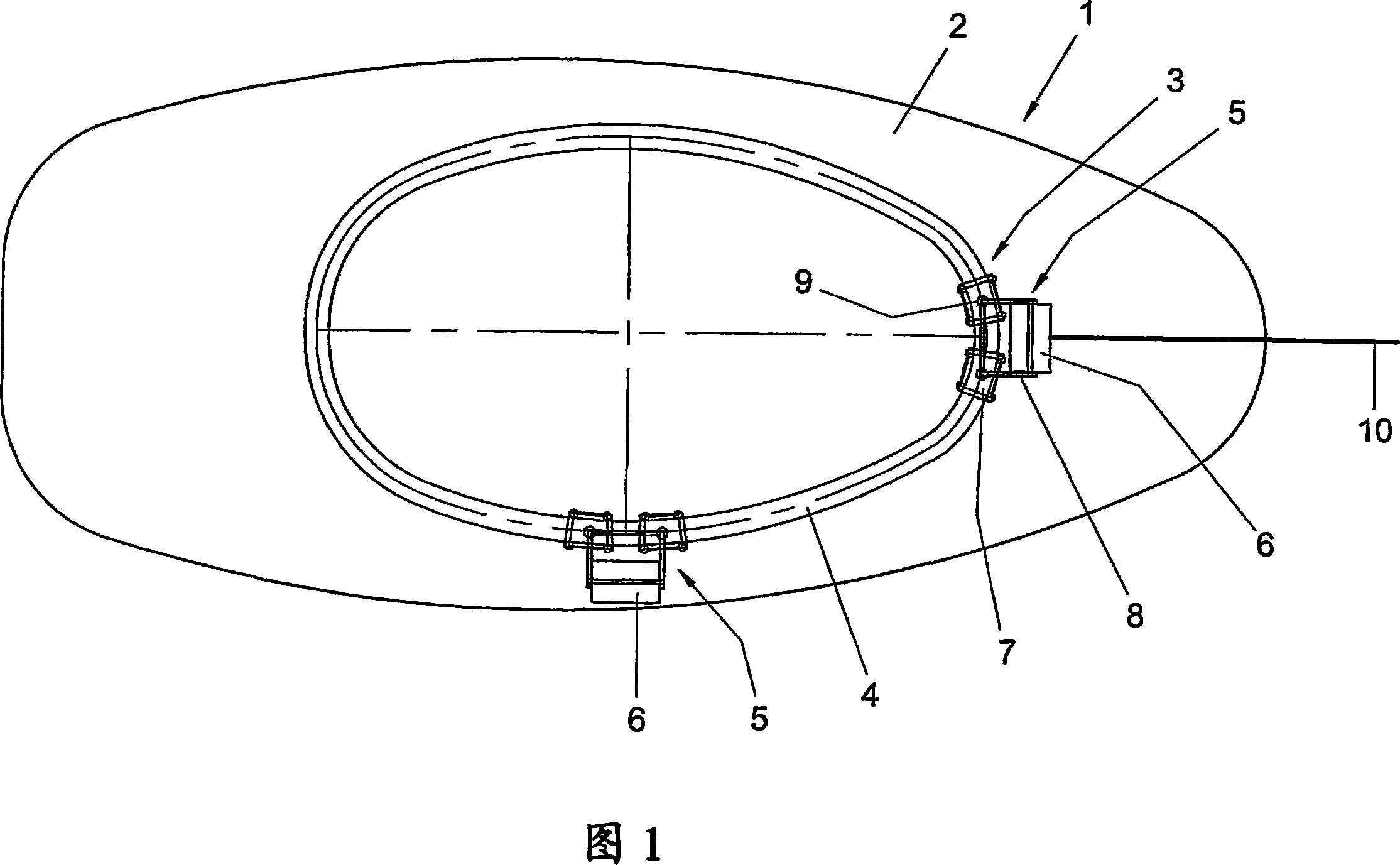
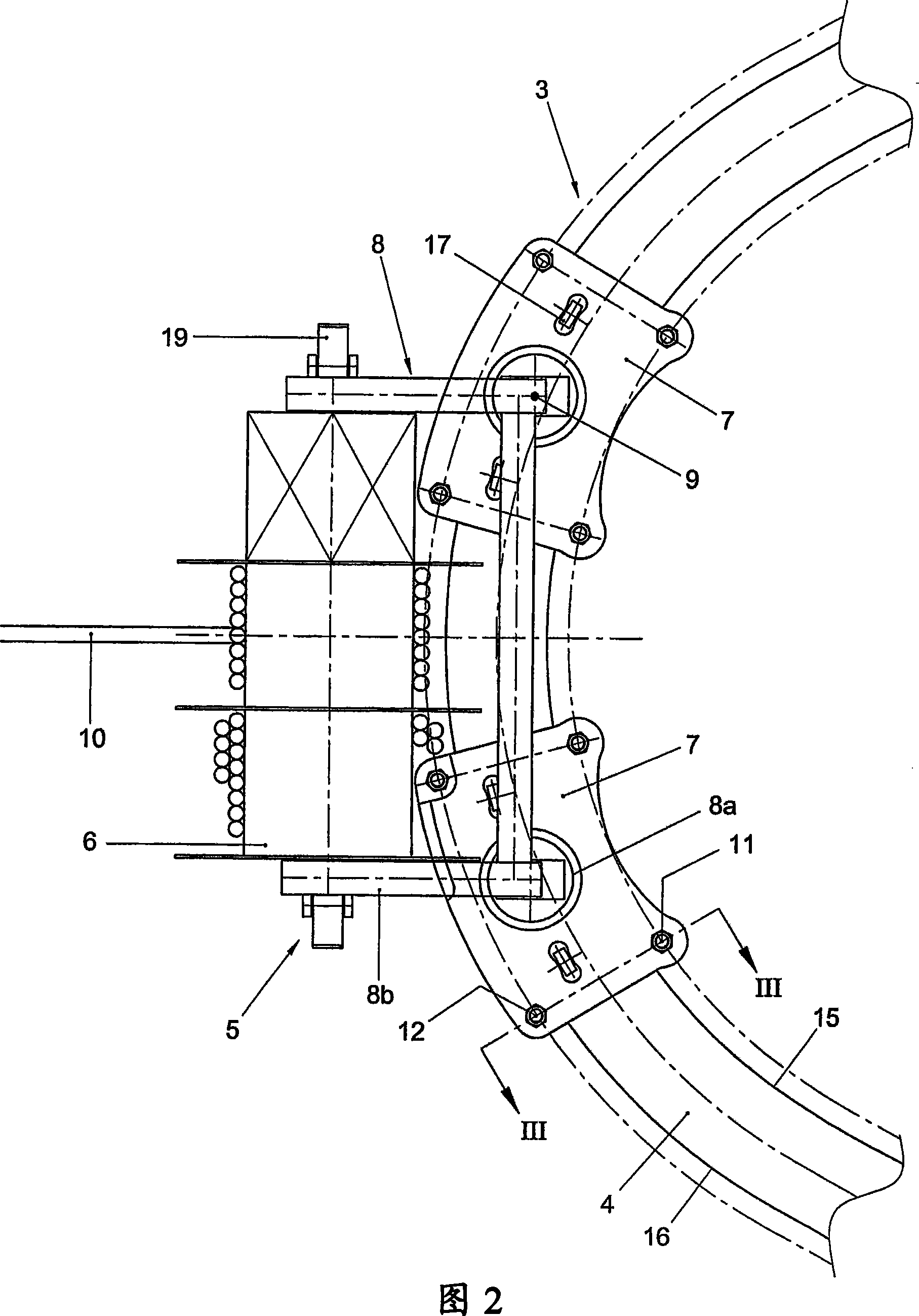
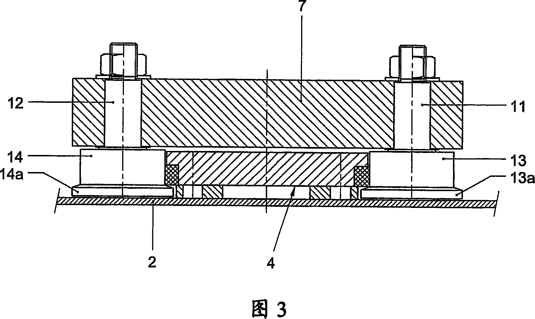
[0023] The tugboat 1 shown in Figure 1 is provided with a deck structure on which a towing device 3 is arranged. The traction device 3 comprises a traction unit in the form of a ring track structure 4 , a seat 5 and a winch 6 . The seat 5 is provided with two mobile units 7 and an intermediate frame 8 hinged to the mobile units 7 about a central axis 9 perpendicular to the drawing plane. The annular track structure 4 forms an oval guideway with a longitudinal axis and a transverse axis, the longitudinal axis extending in the longitudinal direction of the tugboat 1 . The tugboat 1 has a more pointed bow and a blunt stern. Oval rails are suitable for this and are therefore more or less ovoid, the embodiment of which is very suitable for relatively small tugboats.

[0024] The seat 5 with the winch 6 is shown in two different positions, showing how the moving means 7 can be articulated relative to each other and to the intermediate frame 8 so as to follow the curvature of the g...


PUM


Abstract

A tug (1) with a deck construction on which a towing installation (3) is mounted/ which is provided with a seat (5) , a towing unit (6) carried by the seat and an endless rail construction (4) which is fixedly connected to the deck construction and forms a guide track for carrying the seat in a movable manner, so that a force applied to the towing unit can be transmitted via the seat, the rail construction and the deck construction to the tug, while moving the seat along the rail construction depending on the direction of the applied force. The seat is provided with at least two moving units (7) , which are movable in a guided manner through the endless rail construction and are each connected, mutually independently, to the towing unit by a hinge construction with a central axis which extends substantially perpendicularly to a substantially horizontal plane defined by the rail construction.

Description

technical field [0001] The invention relates to a tugboat with a deck structure on which is mounted a traction device provided with a seat, a traction unit supported by the seat and a circular track structure fixedly connected to the deck structure and A rail is formed to movably support the seat so that force applied to the traction unit can be transmitted to the tugboat through the seat, the track structure, and the deck structure while moving the seat along the track structure according to the direction of the applied force. Background technique [0002] For example, it is known from French patent 1,158,501 that for such tugs the towing unit can always be optimally positioned independently of the direction of the applied force or the position of the tug relative to the assisting vessel. Thus, not only is the effective maneuvering capacity of the tugboat increased, but the risk of capsizing is also greatly reduced, especially when the traction cables extend laterally to th...

Claims


Application Information

Patent Timeline
IPC IPC(8): B63B21/56B63B35/68
CPCB63B21/58
Inventor 赫拉尔杜斯·安东尼厄斯·约瑟夫·曼佩利
Owner EURON INTELLIGENCE
Why Eureka
Try Eureka