Quick connect assembly

A technology for electrical devices and contacts, which is applied to parts, electrical components, coupling devices, etc. of connecting devices, which can solve problems such as a lot of installation time.

Inactive Publication Date: 2007-12-26
拉恩科亨
View PDF2 Cites 30 Cited by
  • Summary
  • Abstract
  • Description
  • Claims
  • Application Information

AI Technical Summary

Problems solved by technology

Installing the unit takes a lot of time

Method used


Image

  • Quick connect assembly
  • Quick connect assembly
  • Quick connect assembly

Examples


Embodiment Construction

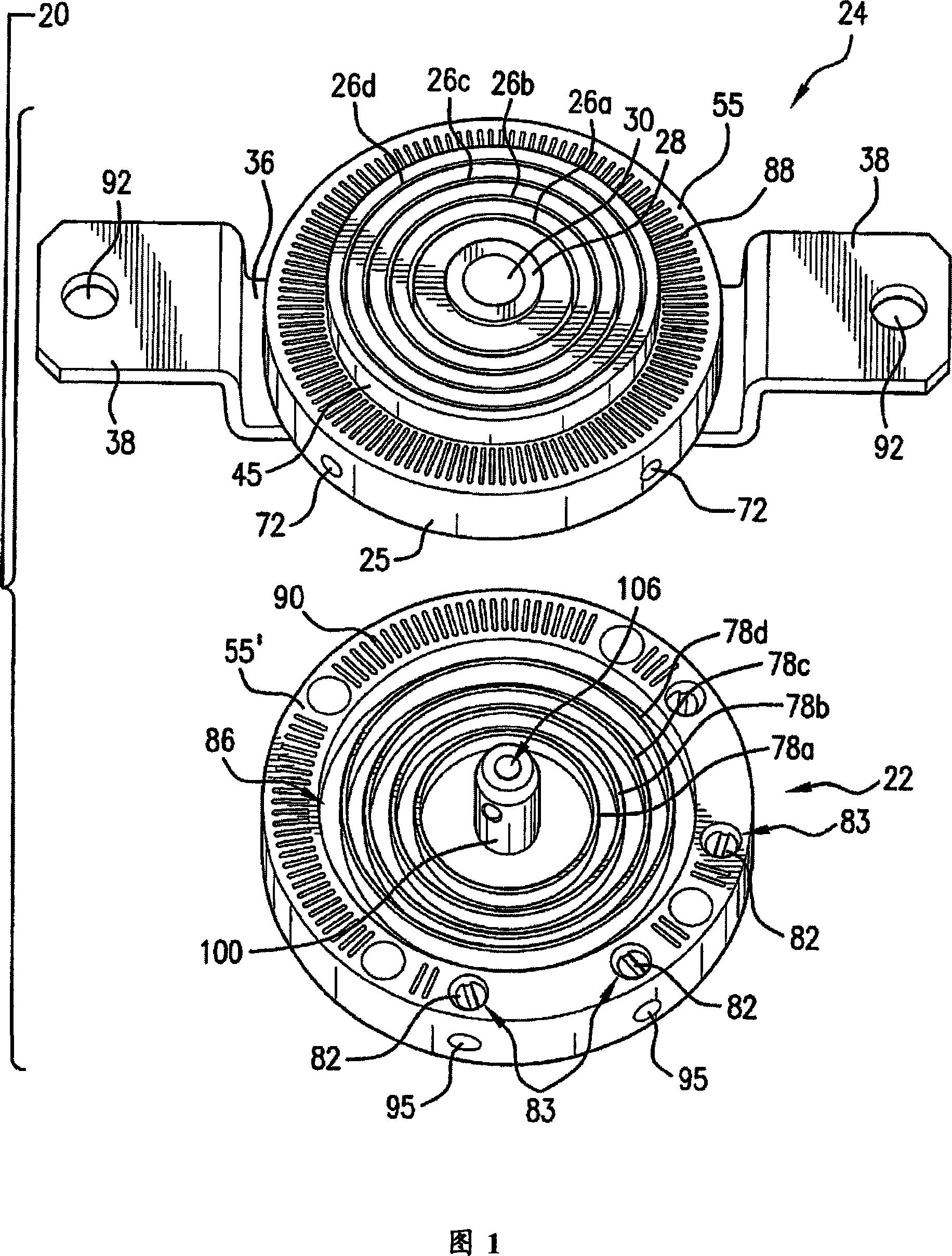
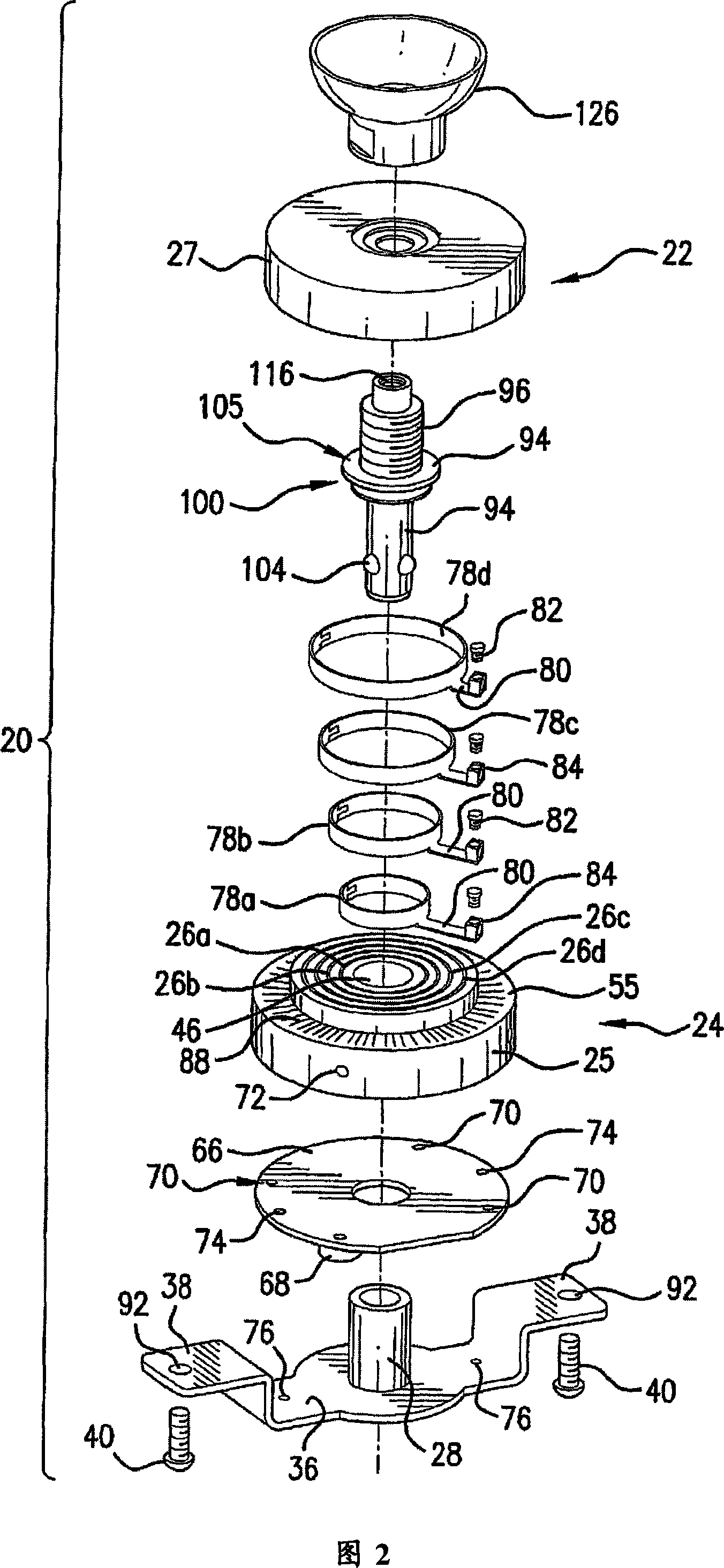
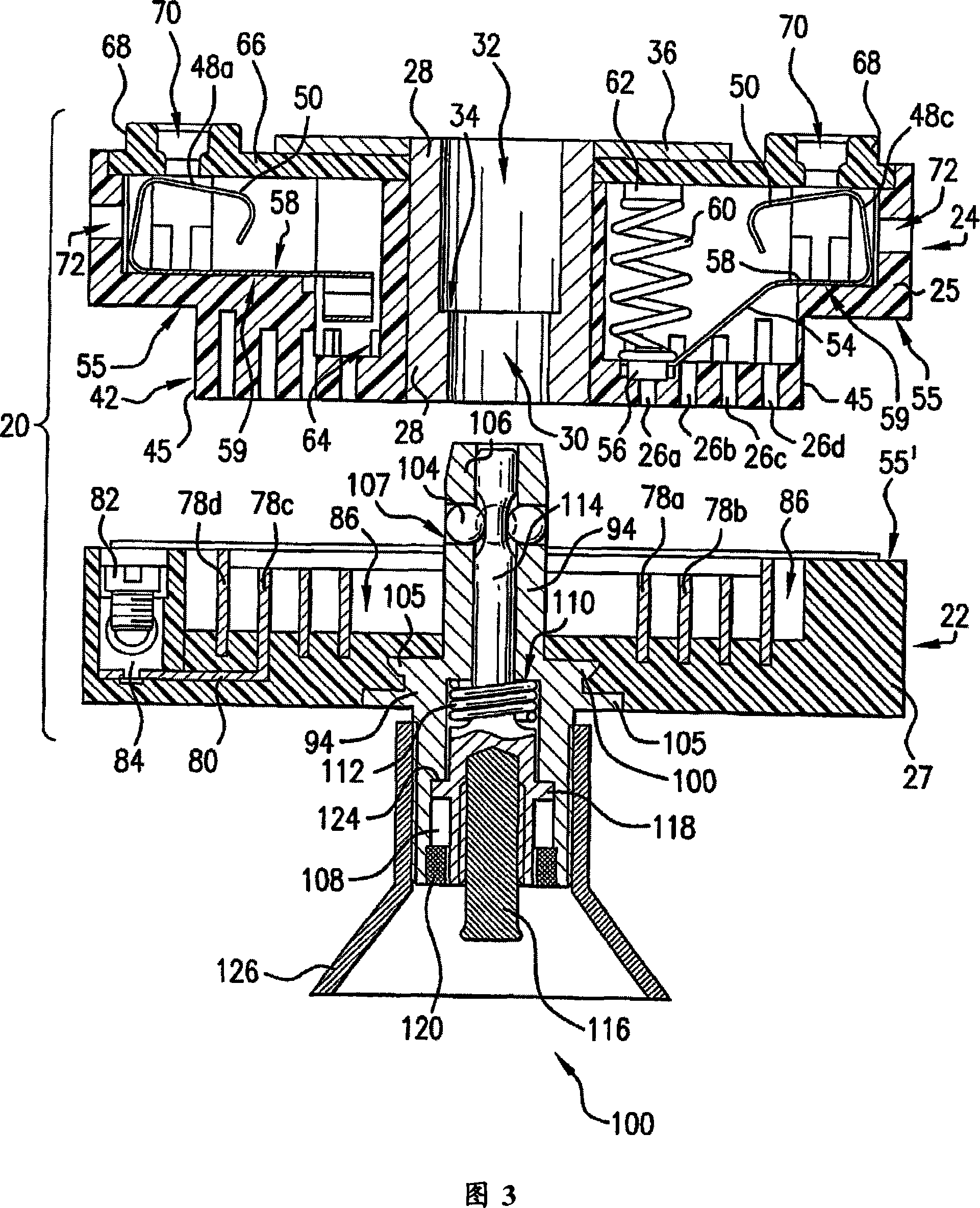
[0066]Referring to FIGS. 1-4 , the quick connection device 20 is used for installing electrical devices, and it includes a plug 22 and a socket 24 . Device 20 is used to electrically connect electrical devices to power lines, and to mechanically support the device on a surface or base, such as a wall, ceiling or floor. The term "device" or "electrical device" means any device, such as a lighting device, ceiling fan, camera, security device or any other device that employs electrical wires, that requires a mechanical connection to support or suspend the device. The plug 22 is fixed to an electrical device (not shown), and the receptacle 24 is fixed to a mounting surface of the device (such as a wall, ceiling or floor), or to a junction box.

[0067] The socket 24 comprises a circular hollow body 25 with a flat circular cover 66, both of which are made of a non-conductive material, such as phenolic resin. Four concentric annular inner grooves 26 a , 26 b , 26 c , 26 d are forme...


PUM


Abstract

A device for connecting and supporting fixtures, such as electrical fixtures, includes a male plug, a mating female socket and a releasable spindle assembly for both holding the plug in the socket and mechanically mounting the fixture on a supporting surface or an electrical box. The plug is provided with concentric, ring shaped male connectors that are matingly received within similarly shaped female recesses in the socket to create electrical connections and also allow the fixture to be rotated to any of a plurality or mounting orientations. The releasable spindle assembly is controlled by the actuation of a push rod operated by a tool or user's finger.

Description

technical field [0001] The invention relates to an electrical connection device and device, in particular to an electrical plug and socket assembly, which can quickly connect and install an electrical device on an electrical outlet. Background technique [0002] Conventional techniques for installing electrical installations, such as installing lighting and fans on walls or ceilings, usually require qualified technicians and use various tools and special hardware. Installing the device requires a considerable amount of time, even by experienced personnel. In addition to manually wiring the unit to the power source, the installer makes special mechanical connections to support or suspend the unit. [0003] In PCT Publication No. WO0016442 ("PCT442"), a solution is proposed, "PCT442" in which a plug and socket combination can be quickly connected to an electrical device and an electrical junction box on a wall or ceiling. The socket is fixed on the wall or on the ceiling clo...

Claims


Application Information

Patent Timeline
IPC IPC(8): H01R13/66
Inventor 拉恩・科亨
Owner 拉恩科亨
Why Eureka
Try Eureka