
Leavers machine and pushing rod for the same

A Levis lace machine and push rod technology, applied in the field of push rods, can solve the problems of expensive equipment, long replacement time, reduced productivity, etc., and achieve the effects of reducing burden, reducing noise, and achieving light weight

Inactive Publication Date: 2010-10-13
MIYAGI LACE CO LTD
View PDF4 Cites 0 Cited by
  • Summary
  • Abstract
  • Description
  • Claims
  • Application Information

AI Technical Summary

Problems solved by technology

Especially in the pushing rod, because the phosphor bronze plate is fixed to the angle iron material by rivets in the past, it cannot be easily replaced by a layman, and it takes a long time to replace it, and the Reves lace machine is stopped during this time. reduce productivity
[0009] In addition, in the case of using a phosphor bronze plate, it becomes very expensive equipment

Method used


Image

  • Leavers machine and pushing rod for the same
  • Leavers machine and pushing rod for the same
  • Leavers machine and pushing rod for the same

Examples


Embodiment Construction

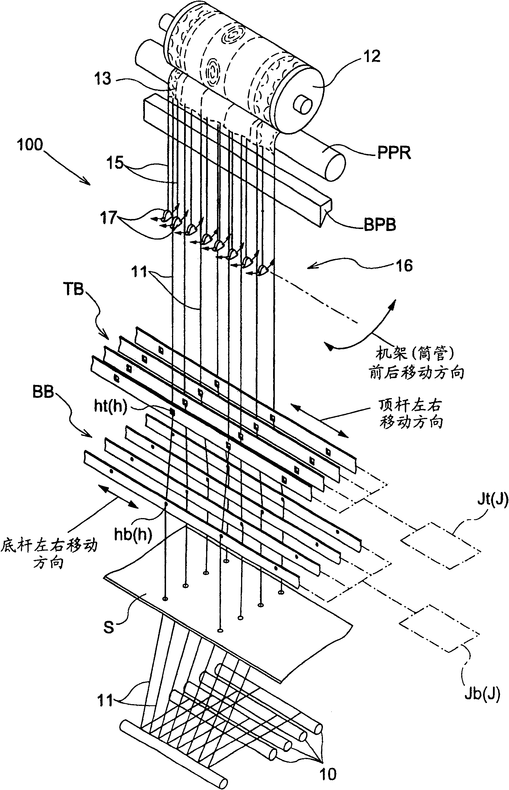
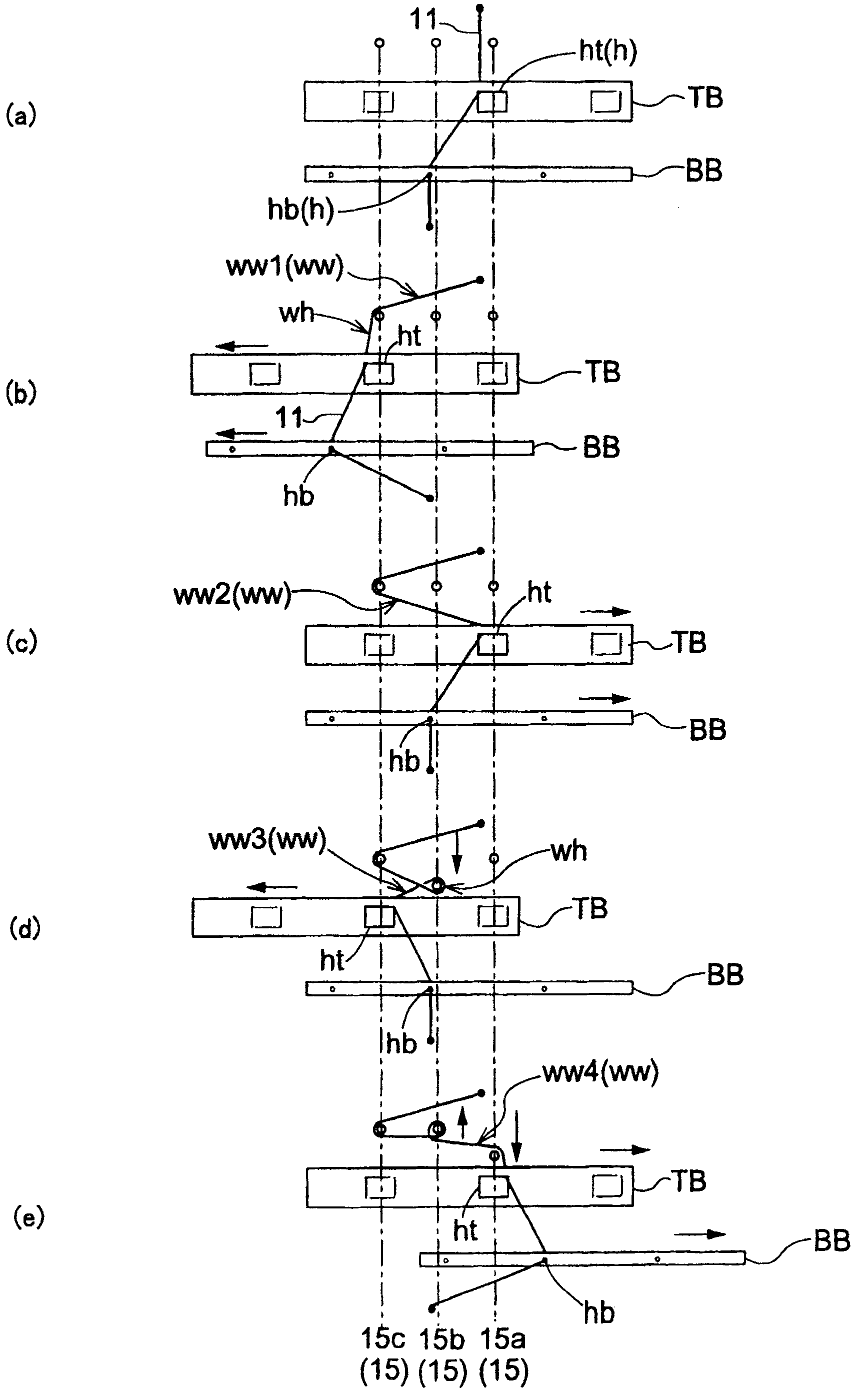
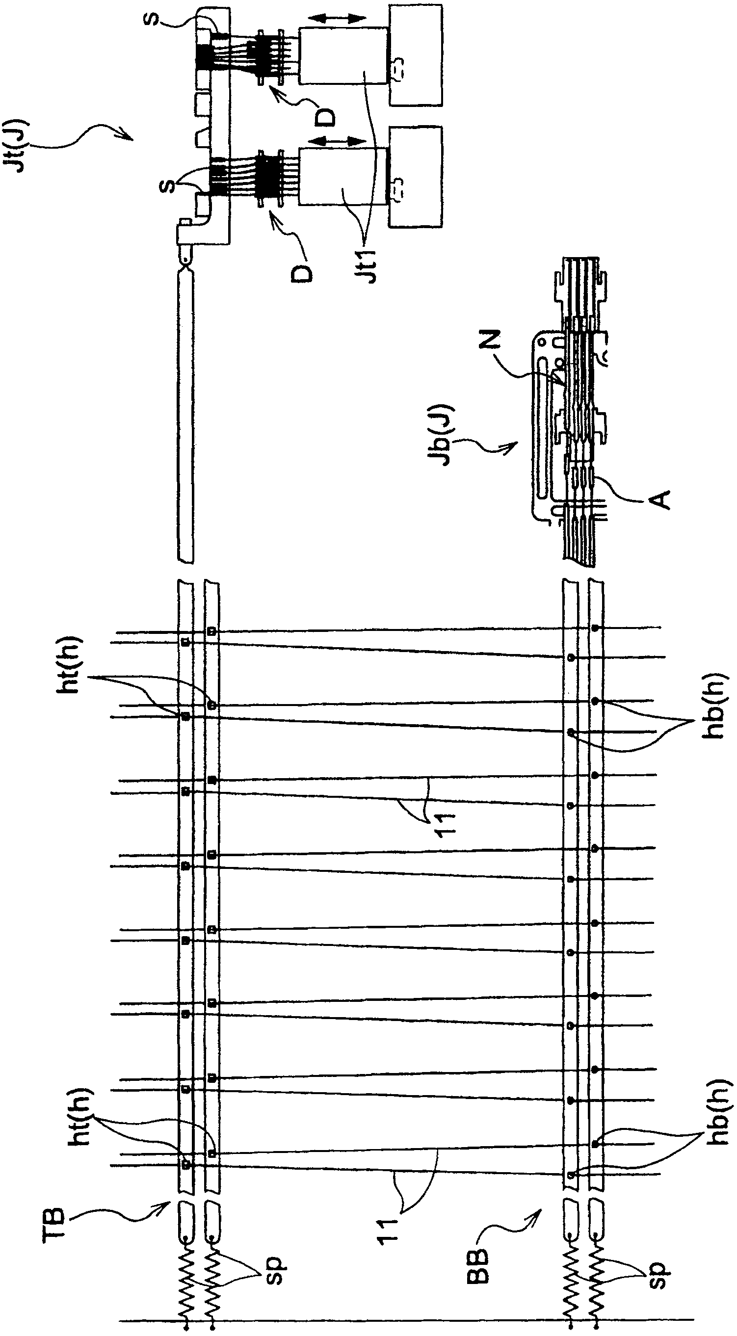
[0040] Next, the Reves lace machine 100 provided with the push rod related to the present application will be described.

[0041] figure 1 The schematic structure of the Reves lace machine 100 is shown, and it is a figure which looked at the Reves lace machine 100 obliquely from front.

[0042] The Reves lace machine 100 guides the warp threads 11 wound on a plurality of warp beams 10 from the lower position of the machine table to the comb tooth part 16 through the sley S, and forms the Leves lace by winding the warp threads 11 and the bobbin line 15 The formed Reves lace 13 is alternately combed and held by the rear dividing reed BPB and the front dividing reed (not shown), and simultaneously lifted by the pin roller PPR on which the card clothing is wound on the upper part. The produced Reves lace 13 has a structure that is wound on the winding roll 12 that is in contact with the needle roll PPR.

[0043] In the Reves Lace Machine 100, use Figure 4 , Figure 5 , Ima...


PUM


Abstract

To provide a game machine capable of reducing a control load on the game control means side and increasing the time for the game control means to spend for the game control. Display control commands at least including a variation time command and a stopped pattern command are transmitted from a game control board to a display control board. Then, whether a prior notice of a ready-to-win state should be given or not, and whether a prior notice of a jackpot should be given or not are determined according to the variation time command, and further, a symbol to be replaced in the symbol replacement control is determined on the display control board side.

Description

technical field [0001] The present invention relates to Reves lace machines and to push rods for use in Reves lace machines. Background technique [0002] The Reves lace machine guides a plurality of warp threads into the comb, and forms Reves lace by winding the warp threads with bobbin threads. That is, in the Reves lace machine, the warp thread is moved and positioned in the left and right direction of the Reves lace machine, and the bobbin line is swung in the front and rear direction of the Reves lace machine, and is formed by appropriately setting the timing of the two actions. Reves lace. [0003] The bobbin on which the above-mentioned bobbin line is wound is accommodated in a frame, and the delivery of the bobbin line occurs by swinging the frame in the front-rear direction of the Reves lace machine. And, the swing of the frame is controlled by the action of the push rod. That is, the engaging portion provided on the frame and the pressing engaging portion provid...

Claims


Application Information

Patent Timeline
Patent Type & Authority Patents(China)
IPC IPC(8): D04C3/00
CPCD04C5/02D04C5/16
Inventor 泽村彻弥
Owner MIYAGI LACE CO LTD
Learn More