

Laser processing device
A laser processing and power device technology, applied in the laser field, can solve the problems of low laser processing efficiency, save replacement time and improve processing efficiency
- Summary
- Abstract
- Description
- Claims
- Application Information
AI Technical Summary
Problems solved by technology
Method used
Image

Examples
Embodiment Construction
[0021] In order to make the object, technical solution and advantages of the present invention clearer, the present invention will be further described in detail below in conjunction with the accompanying drawings and embodiments. It should be understood that the specific embodiments described here are only used to explain the present invention, not to limit the present invention.
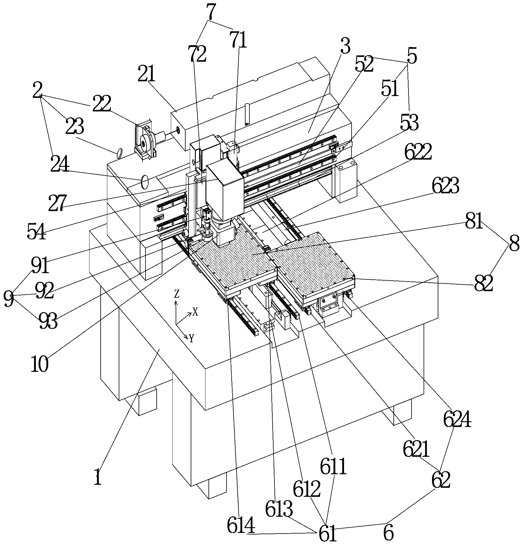
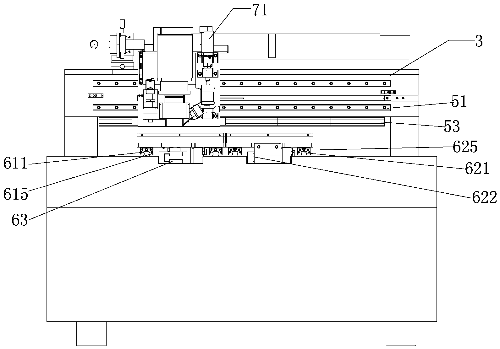
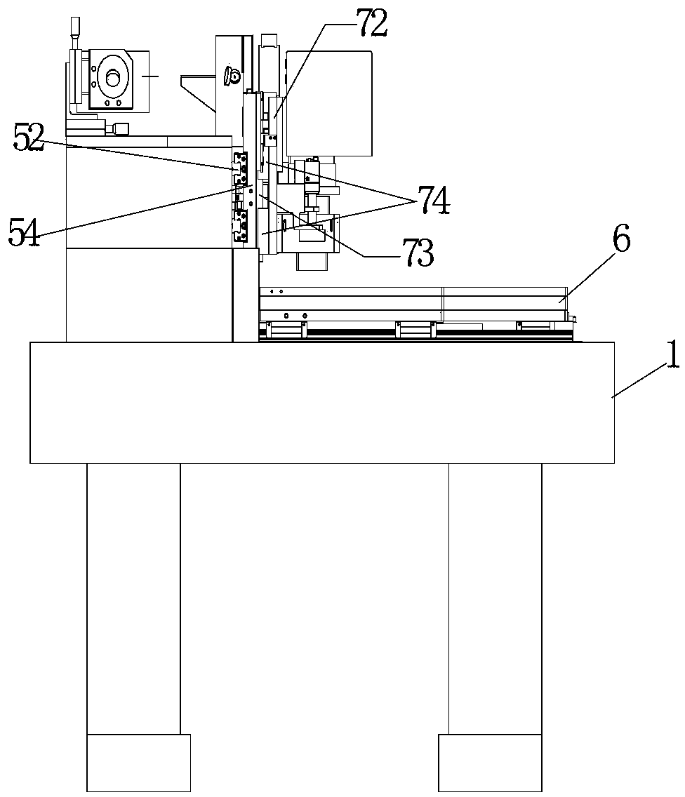
[0022] see figure 1 and Figure 5 As shown, the embodiment of the present invention provides a laser processing device, including a bed 1, a beam 3, a laser processing system and a software control system (not shown in the figure), the laser processing system includes an optical transmission system 2 and a laser processing assembly , the bed 1 is provided with at least two movable positioning work platforms 8; the laser processing assembly is provided on the beam 1, and can move back and forth on the beam 1, when the laser processing assembly completes a positioning work After the workpiece on th...
PUM
 Abstract
Description
Claims
Application Information