Device and method for controlling internal combustion engine

a technology of internal combustion engine and control device, which is applied in the direction of electrical control, process and machine control, instruments, etc., can solve the problems of difficult to achieve the transition state such as acceleration, the effect of suppressing the torque fluctuation of the internal combustion engin

Active Publication Date: 2007-04-24
TOYOTA JIDOSHA KK
View PDF16 Cites 17 Cited by
  • Summary
  • Abstract
  • Description
  • Claims
  • Application Information

AI Technical Summary

Benefits of technology

[0007]From the foregoing, an object of the present invention is to provide a device and a method for controlling an internal combustion engine, capable of satisfactorily suppressing torque fluctuation of the internal combustion engine or deviation from a target air-fuel ratio when switching between a port injector and an in-cylinder injector is made or a fuel injection ratio between the port injector and the in-cylinder injector is considerably fluctuated.
[0010]In the internal combustion engine including the control device described above, when the internal combustion engine enters the transition state such as acceleration, the load estimation unit estimates a load factor, and a fuel injection ratio between the port injector and the in-cylinder injector is calculated based on an estimated value of the load factor (an estimated load factor). Therefore, when the fuel injection ratio between the port injector and the in-cylinder injector is changed in the transition state (including switching between the port injector and the in-cylinder injector), one or both of the port injector and the in-cylinder injector quickly injects the fuel in an appropriate quantity in accordance with the fuel injection ratio calculated based on the estimated load factor. As such, the control device can satisfactorily suppress torque fluctuation of the internal combustion engine or deviation from a target air-fuel ratio when the fuel injection ratio is changed (switching between the injectors is made) in the transition state.
[0012]With such a configuration, when an amount of fluctuation from a previous fuel injection ratio calculated by the injection ratio calculation unit is not larger than the prescribed value, no change in the fuel injection ratio between the port injector and the in-cylinder injector (switching between the port injector and the in-cylinder injector) is made. Accordingly, as the number of times of change in the fuel injection ratio (switching between the injectors) can be decreased, a probability of occurrence of torque fluctuation of the internal combustion engine or deviation from a target air-fuel ratio can be lowered.
[0013]Preferably, the internal combustion engine is applied to a vehicle including a cruise control system allowing automatic cruise drive, and the injection ratio setting unit prohibits change in the fuel injection ratio between the port injector and the in-cylinder injector when the determination unit has determined that the operation state of the internal combustion engine does not exhibit the transition state and while the cruise control system is actuated.
[0015]Accordingly, while the operation state of the internal combustion engine does not exhibit the transition state and the cruise control system is actuated, change in the fuel injection ratio between the port injector and the in-cylinder injector is preferably prohibited. By prohibiting change in the fuel injection ratio (switching between the injectors) during actuation of the cruise control system, frequency that the human body feels shock due to torque fluctuation or deviation of an air-fuel ratio caused by change in the fuel injection ratio can be lowered.
[0018]In the internal combustion engine including the control device, at the timing of shift change, the load estimation unit estimates a load factor of the internal combustion engine, and a fuel injection ratio between the port injector and the in-cylinder injector is calculated based on an estimated value of the load factor (estimated load factor). In addition, change in the fuel injection ratio (switching between the injectors) is made substantially simultaneous to the shift change, and one or both of the port injector and the in-cylinder injector quickly injects the fuel in an appropriate quantity in accordance with the fuel injection ratio calculated based on the estimated load factor. Therefore, the control device can satisfactorily suppress torque fluctuation of the internal combustion engine or deviation from a target air-fuel ratio when the fuel injection ratio is changed (switching between the injectors is made). In addition, even if slight torque fluctuation takes place due to change in the fuel injection ratio, it can be cancelled by shock at the time of shift change tolerable in terms of human perception.

Problems solved by technology

Accordingly, even if switching from the in-cylinder injector to the port injector is delayed as in the conventional internal combustion engine described above, satisfactory suppression of torque fluctuation of the internal combustion engine or deviation from a target air-fuel ratio in a transition state such as acceleration has been difficult to achieve.

Method used


Image

  • Device and method for controlling internal combustion engine
  • Device and method for controlling internal combustion engine
  • Device and method for controlling internal combustion engine

Examples


Embodiment Construction

[0034]A best mode for carrying out the present invention will be described hereinafter with reference to the drawings.

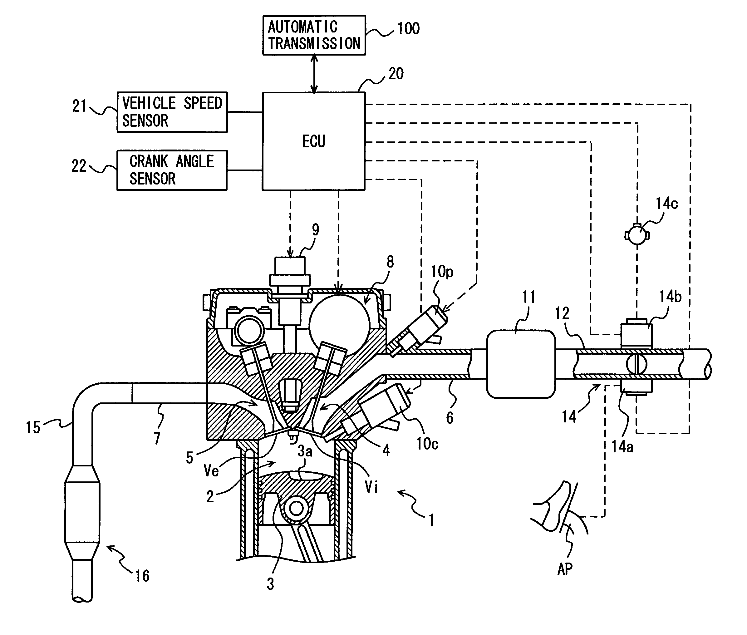
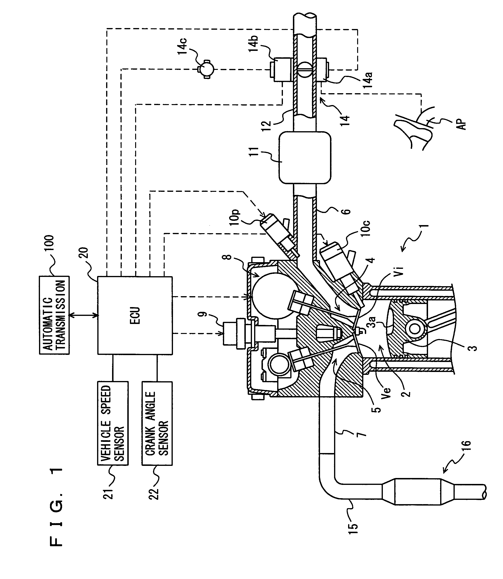
[0035]FIG. 1 is a schematic diagram of a configuration of an internal combustion engine to which a control device according to the present invention is applied. An internal combustion engine 1 shown in FIG. 1 is implemented as a multi-cylinder internal combustion engine for a vehicle (for example, a 4-cylinder internal combustion engine, although FIG. 1 shows only one cylinder). Internal combustion engine 1 receives power from a not-shown crankshaft, as a result of reciprocating motion of a piston 3 caused by combustion of an air-fuel mixture in each combustion chamber2. Though internal combustion engine 1 is herein described as what is called a gasoline engine, the present invention is not limited thereto and the present invention is naturally applicable also to a diesel engine.

[0036]As shown in FIG. 1, an intake port 4 communicating to each combustion chamber 2 is ...


PUM


Abstract

An internal combustion engine includes a port injector injecting a fuel into an intake port, an in-cylinder injector directly injecting a fuel into a combustion chamber, and an ECU. When the ECU determines that an operation state of the internal combustion engine exhibits a transition state, the ECU obtains an estimated load factor of the internal combustion engine based on the operation state of the internal combustion engine, and calculates a fuel injection ratio between the port injector and the in-cylinder injector based on the estimated load factor.

Description

[0001]This nonprovisional application is based on Japanese Patent Application No. 2004-226035 filed with the Japan Patent Office on Aug. 2, 2004, the entire contents of which are hereby incorporated by reference.BACKGROUND OF THE INVENTION[0002]1. Field of the Invention[0003]The present invention relates to a device and a method for controlling an internal combustion engine including a port injector injecting a fuel into an intake port and an in-cylinder injector directly injecting a fuel into a combustion chamber.[0004]2. Description of the Background Art[0005]An internal combustion engine including a port injector injecting a fuel into an intake port and an in-cylinder injector directly injecting a fuel into a combustion chamber has conventionally been known (see, for example, Japanese Patent Laying-Open No. 63-255539). In the internal combustion engine, fuel injection is switched between the in-cylinder injector and the port injector, depending on a load. In addition, when switch...

Claims


Application Information

Patent Timeline
Patent Type & Authority Patents(United States)
IPC IPC(8): F02B7/00F02B7/04B60K31/00F02D41/02F02D41/30
CPCF02D41/023F02D41/10F02D41/3005F02D41/307F02D41/3094F02D2200/501Y02T10/84F02D2041/1412
Inventor MARUYAMA, KENYA
Owner TOYOTA JIDOSHA KK
Why Eureka
Try Eureka