Method for operating an actuator, especially an electric actuator in a stabilizer arrangement

a technology of stabilizer arrangement and actuator, which is applied in the direction of cycle equipment, instruments, transportation and packaging, etc., can solve the problems of large engine power, large amount of engine power, and large amount of control movement or control force of the actuator

Active Publication Date: 2011-07-19
ZF FRIEDRICHSHAFEN AG
View PDF17 Cites 1 Cited by
  • Summary
  • Abstract
  • Description
  • Claims
  • Application Information

AI Technical Summary

Benefits of technology

[0010]The task of the present invention is to change the resonance behavior of the stabilizer arrangement in such a way that the motor vehicle body movements are comfortable during operation of the motor vehicle.
[0012]In a conventional actuator control system, the required torque is determined on the basis of several components, namely, the mass moment of inertia of the actuator, frictional torques within the stabilizer arrangement, and a motor vehicle level component, that is, the instantaneous roll position. It is possible in this way to achieve satisfactory suppression of a rolling movement of the motor vehicle body as it travels around a curve.
[0013]Whenever there is an elastic deflection of a wheel on one side, the stabilizer sections execute torsional movement with respect to each other, which is transmitted to the actuator. This torsional movement of the stabilizer section leads to an opposite operating movement of the actuator. The weighting factor has the effect of damping the influence of the elastic deflection on the grand total of the actuator torque. For a passenger in the motor vehicle, this method means that, when there is an inward elastic deflection of a wheel on one side of the motor vehicle, the supporting torque acting in the direction opposite the rolling movement will still increase, but it will not increase abruptly, which means that more comfortable driving behavior is achieved.
[0016]By providing this variable, the spring rate of the stabilizer sections can be modified on the basis of calculations performed in the electronic control system without the need to make any physical changes to the components.
[0019]It is therefore possible to adapt the system behavior of the torsional oscillator as desired by means of active intervention in the engine torque with the goal of achieving optimal, application-specific adaptation of the measures described above.
[0020]Because the necessary sensor system is already present, it is especially advantageous here for the actuator movement to be detected as the rotational angle of the electric motor. In theory, a servo cylinder could also be used to generate a torsional movement in a stabilizer arrangement. In that case, however, the axial movement of the servo cylinder would have to be converted to a rotational angle. According to an advantageous embodiment, the difference angle is detected by a sensor installed functionally between the stabilizer sections which rotate relative to each other. The sensor can be installed inside the actuator and thus be well protected. Another advantageous measure consists in using the sensor system required for the desired command action to optimize the action of the disturbance variable as well.

Problems solved by technology

When the actuator is under open-loop or closed-loop control without consideration of these facts, the actuator executes very large control movements or exerts very large control forces, which are transmitted to the motor vehicle body and are perceived as uncomfortable by the passengers.
One disadvantage of this solution is that, in an active sense, a large amount of engine power, corresponding to the power loss due to the gearing, is required to move the actuator.
A second disadvantage is that the active stabilizer acts for the most part as a passive stabilizer when excited by the road.
Increasing the cross section, however, is frequently associated with a disadvantageous increase in weight or in the amount of space occupied.
A high-powered actuator is either very expensive or very bulky.
This, however, leads to a loss of important data describing the rolling behavior of the motor vehicle body, and these data are therefore unavailable to the stabilizer control system.

Method used


Image

  • Method for operating an actuator, especially an electric actuator in a stabilizer arrangement
  • Method for operating an actuator, especially an electric actuator in a stabilizer arrangement
  • Method for operating an actuator, especially an electric actuator in a stabilizer arrangement

Examples


Embodiment Construction

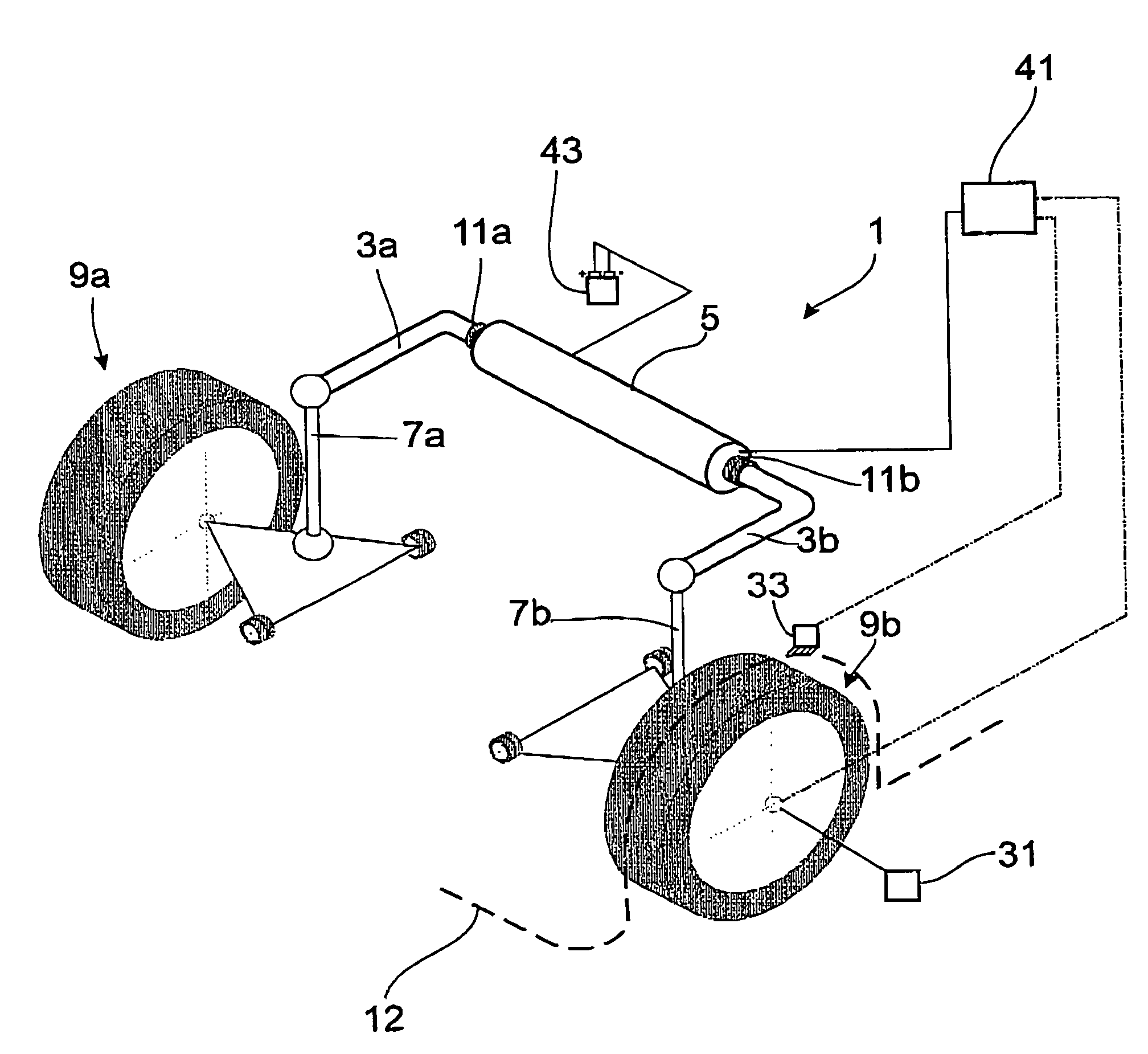
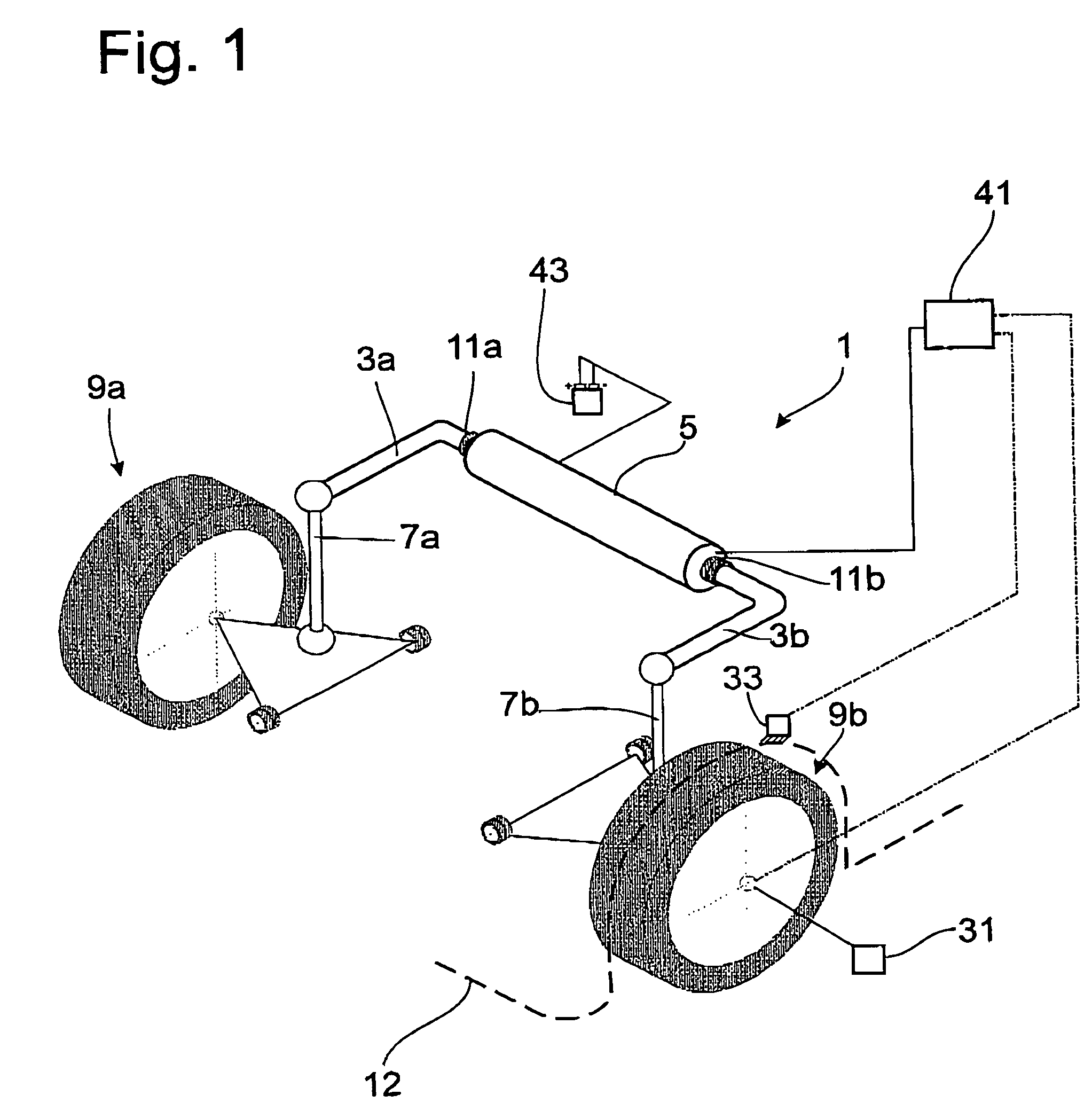
[0027]FIG. 1 shows a schematic diagram of a stabilizer arrangement 1, which comprises a two-part stabilizer with stabilizer sections 3a; 3b and an actuator 5, installed between the two stabilizer sections. Each stabilizer section 3a; 3b is connected to a motor vehicle wheel 9a; 9b by a rocker post 7a; 7b. Two stabilizer bearings 11a; 11b connect the stabilizer arrangement to a motor vehicle body 12. When one of the motor vehicle wheels 9a; 9b is deflected elastically inward or outward or when the motor vehicle body executes a rolling movement around the longitudinal axis, the corresponding stabilizer section 3a; 3b is subjected to torsion as a function of the length ratios.

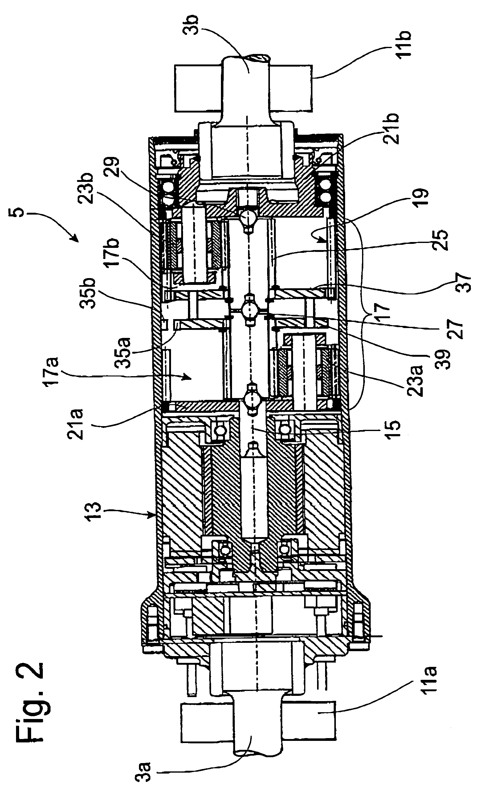
[0028]FIG. 2 is limited to a longitudinal cross section through the actuator 5. In a housing 13, an electric oscillating motor with a rotor shaft 15 is provided to adjust the stabilizer arrangement. The stabilizer section 3a is permanently connected to the housing 13 of the oscillating motor. Between the rotor sha...


PUM


Abstract

Method for operating an adjustable stabilizer arrangement including an actuator, which applies actuator torque to stabilizer sections as a function of a command variable to influence the rolling movement of a motor vehicle body, where sensors are used to detect the movement of the motor vehicle body and the movements of the wheels. An operating condition of the actuator supplies a variable which can be used to determine the actuator torque, upon which is superimposed an adjustment signal for the actuator, and where the variable is modified by a weighting factor.

Description

BACKGROUND OF THE INVENTION[0001]1. Field of the Invention[0002]The invention pertains to a method for operating an adjustable stabilizer arrangement in a motor vehicle having a body and wheels, wherein the arrangement includes a pair of stabilizer sections connected to respective wheels on an axle of a vehicle, and an actuator having an electric motor for applying torque to the stabilizer sections.[0003]2. Description of the Related Art[0004]A stabilizer arrangement with an electric actuator is known from US 2007 / 0114733, where a rolling motion of the motor vehicle body is to be counteracted by means of automatic control of the actuator. A motor vehicle body, however, rolls not only when traveling around a curve but also while traveling straight ahead, i.e., when a wheel on one side is elastically deflected. It must be kept in mind here that the motor vehicle body moves at a frequency on the order of up to 1 Hz, whereas the frequency of the elastic deflection of a wheel can be as h...

Claims


Application Information

Patent Timeline
Patent Type & Authority Patents(United States)
IPC IPC(8): B60G17/018
CPCB60G17/0162B60G17/019B60G21/0555B60G21/0558B60G2202/135B60G2202/42B60G2204/62B60G2204/82B60G2204/8302B60G2400/104B60G2400/98B60G2600/172B60G2600/85B60G2800/012B60G2800/0122B60G2800/24B60G2800/9122
Inventor KETTELER, KARL-HERMANNFUESSL, ANDREASSCHMID, JOHANNES
Owner ZF FRIEDRICHSHAFEN AG
Why Eureka
Try Eureka