Video signal processing method and device

a video signal and processing method technology, applied in the direction of signal generators with optical-mechanical scanning, picture reproducers using projection devices, television systems, etc., can solve the problems of picture quality deterioration described above, too high intensity level at the edge portion, and liable to be noticed, so as to achieve satisfactory suppression of overemphasized components, simple structure of making, and satisfactory detection

Inactive Publication Date: 2007-05-22
SONY CORP
View PDF15 Cites 0 Cited by
  • Summary
  • Abstract
  • Description
  • Claims
  • Application Information

AI Technical Summary

Benefits of technology

[0016]The first aspect of the present invention is a video-signal processing method comprising a number-of-scanning-line conversion step of converting the number of scanning lines of video signal, an emphasis step of emphasizing a high-frequency component at least in a vertical direction of the video signal converted in the number-of-scanning-line conversion step, a delay step of obtaining a delay signal delayed by a plurality of stages of time equal to or more than a time required for converting in the number-of-scanning-line conversion step, a selection step of selecting an appropriate delay signal from among the plurality of delay signals obtained in the delay step, a detection step of detecting an overemphasized component by comparing the delay signal selected in the selection step with the video signal emphasized in the emphasis step, and a suppression step of suppressing the emphasis with respect to a portion where the overemphasized component is detected in the detection step. By arranging in this way, it is possible to select a satisfactory signal to be compared with the emphasized component by selecting the appropriate delay signal from among the plurality of stages of delay signals and make satisfactory suppression of the overemphasized component for enhancing picture quality.
[0017]The second aspect of the present invention is such that, in the video-signal processing method according to the first aspect of the invention, the plurality of stages of delay signals in the delay step are a signal delayed by about a time required for converting in the number-of-scanning-line conversion step, and a signal further delayed by about one field period from the signal delayed by about the time required for converting in the number-of-scanning-line conversion step. By arranging in this way, a signal of one field before or one frame before can be utilized for detecting the emphasized component, so that a satisfactory signal to be compared with the emphasized component can be selected.
[0018]The third aspect of the present invention is such that, in the video-signal processing method according to the first aspect of the invention, the plurality of stages of delay signals in the delay step are a signal delayed by about a time required for converting in the number-of-scanning-line conversion step and a signal further delayed by about one field period from the signal delayed by about a time required for converting in the number-of-scanning-line conversion step, and in the selection step, a higher signal in level is selected from the two delay signals. By doing in this way, it is possible to select an appropriate delay signal by comparatively simple structure of making a mere level comparison.

Problems solved by technology

Thus, if the high-frequency component in the vertical direction is emphasized in such picture, an intensity level at the edge portion will be too high and become liable to be noticed.
In addition, such picture-quality deterioration will also be caused, in the other case than the above-described telop, for example, when the menu for adjusting a television set is superimposed on a natural picture for display.
In these cases, the picture-quality deterioration described above will be caused likewise.
Because of this fact, exact detection of emphasized component cannot be made, so that a properly emphasized component may be suppressed by mistake, or inversely the overemphasized component may not be suppressed, which will lead to picture-quality deterioration.
Moreover, when a phase of scanning lines created by the scanning-line conversion differs from a phase of input signal, only by comparing with the input signal delayed by the same time as that required for the number-of-scanning-line conversion process, the exact detection of emphasized component cannot be performed.
This also poses the same problem that the duly emphasized component is suppressed erroneously or the overemphasized component cannot be suppressed.

Method used


Image

  • Video signal processing method and device
  • Video signal processing method and device
  • Video signal processing method and device

Examples


first embodiment

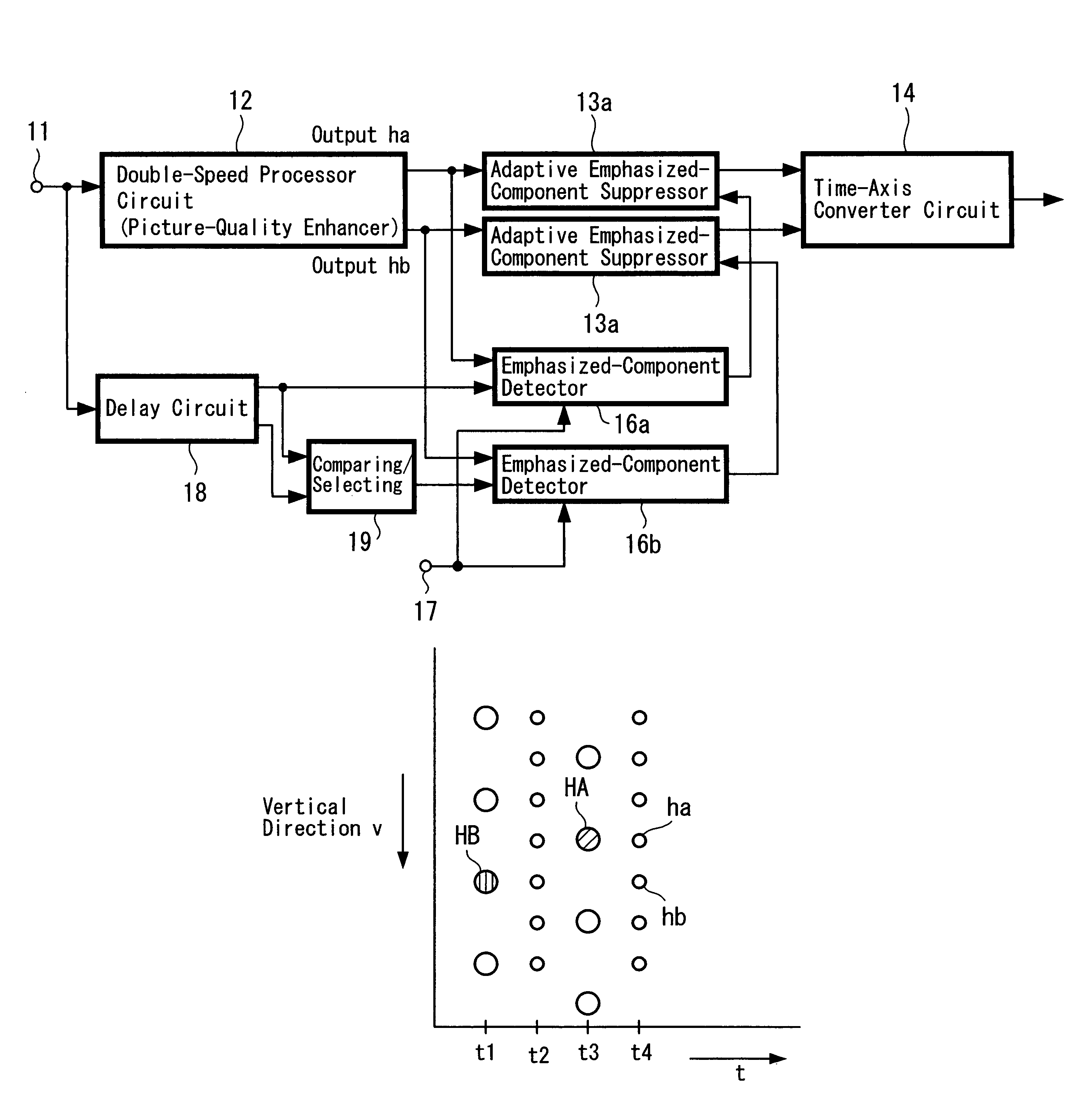
[0033]The first embodiment according to the present invention will be described below with reference to FIGS. 3 to 5.

[0034]FIG. 3 is a diagram showing a structure example for making video-signal processing according to this embodiment. Circuits of this embodiment are those applied to a television set and the like, in which a video signal or the like received by a tuner is supplied to an input terminal 11. The video signal obtained at the input terminal 11 is supplied to a double-speed processor circuit 12 which performs the so-called double-speed conversion processing to double the number of scanning lines. In this case, the video signal obtained at the input terminal 11 is a digitized video signal and the double-speed conversion processing is performed in a digital form. When the double-speed processor circuit 12 performs the double-speed conversion processing, it also performs the picture-quality enhancement processing. This picture-quality enhancement processing may sometimes be ...

second embodiment

[0049]Next, the second embodiment according to the present invention will be described with reference to FIGS. 6 and 7.

[0050]FIG. 6 is a diagram showing a structure example of performing video-signal processing according to this embodiment. In this example, a video signal obtained at an input terminal 21 is supplied to a time-axis converter circuit 22, which performs processing of converting twice the number of scanning lines of the input video signal. However, this circuit 22 performs only time-axis conversion processing which repeats a signal of the same line merely twice to output. The signal converted twice in the number of scanning lines by the time-axis converter circuit 22 is supplied to a number-of-scanning-line converter circuit 23 for picture-quality enhancement processing. In this processing to enhance picture quality, signals of the adjacent line, signals of the adjacent field or the like are referred to.

[0051]The video signal double-speed-converted and enhanced in pictu...


PUM


Abstract

To enable a satisfactory suppression of overemphasized component after converting the number of scanning lines of video signal, when the video signal is converted in the number of scanning lines and a high-frequency component at least in a vertical direction of the converted video signal is emphasized, signals delayed by a plurality of stages of time equal to or more than a time required for converting the number of scanning lines are obtained by a delay circuit 18, and an appropriate delay signal is selected from among the plurality of delay signals by a selection circuit 19. The selected delay signal is compared with the emphasized video signal in emphasized-component detector circuits 16a, 16b and the overemphasized component is detected. Processing to suppress the emphasis is performed by suppressor circuits 13a, 13b with respect to a portion where the overemphasized signal component is detected.

Description

TECHNICAL FIELD[0001]The present invention relates to a video-signal processing method and apparatus, particularly to a processing technique for suppressing adaptively an excessive emphasis of signal when the number of scanning lines of a video signal is converted twice by a double-speed conversion and the like for making an enhancement processing of its picture-quality.BACKGROUND ART[0002]As a number-of-scanning-line conversion apparatus for converting, for example, 525 scanning lines per frame of video signal on NTSC system or 625 scanning lines per frame of video signal on PAL system to 1050 or more scanning lines, such apparatus that classifies an input picture depending on its pattern and processes every pattern so as to make the picture have higher definition was proposed in the past (Japanese Laid-Open Patent Application No. H7-75066).[0003]By employing such number-of-scanning-line conversion apparatus, it is possible to improve remarkably the quality of, for example, natural...

Claims


Application Information

Patent Timeline
Patent Type & Authority Patents(United States)
IPC IPC(8): H04N5/00H04N11/20H04N5/21H04N7/01H04N5/20H04N5/208
CPCH04N5/20H04N5/208H04N7/01H04N7/012
Inventor IMAI, SEIKOSARUGAKU, TOSHIOKANEKO, NAOKIHOSHINO, TAKAYA
Owner SONY CORP
Why Eureka
Try Eureka