Control device and control method for lockup clutch

a technology of control device and lockup clutch, which is applied in the direction of clutches, gearing elements, gearing, etc., can solve the problems that the occupant of the vehicle may feel uncomfortable due to rotation fluctuations, and the occupant of the vehicle may similarly feel uncomfortabl

Active Publication Date: 2015-03-17
AISIN AW CO LTD
View PDF11 Cites 1 Cited by
  • Summary
  • Abstract
  • Description
  • Claims
  • Application Information

AI Technical Summary

Benefits of technology

[0005]It is a primary object of the present invention to more properly stop slip control in order to protect a lockup clutch.
[0008]This control device for the lockup clutch determines whether to fully engage or disengage the lockup clutch according to at least the state of the motor if the clutch temperature becomes equal to or higher than the predetermined temperature during execution of the slip control. Thus, when the slip control is stopped to protect the lockup clutch, one of full engagement and disengagement of the lockup clutch which can more satisfactorily suppress manifestation of, e.g., rotation fluctuations, change in noise, vibrations, etc. of the motor can be selected according to at least the state of the motor. This can reduce the possibility of making an occupant of the vehicle feel uncomfortable by stopping of the slip control. According to this control device for the lockup clutch, the slip control can therefore be more properly stopped to protect the lockup clutch.
[0010]The determining means may determine that the lockup clutch should be fully engaged if the input torque is larger than predetermined torque or the rotational speed of the motor is higher than a predetermined rotational speed, and may determine that the lockup clutch should be disengaged if the input torque is equal to or smaller than the predetermined torque and the rotational speed of the motor is equal to or lower than the predetermined rotational speed. Whether the lockup clutch should be fully engaged or disengaged can thus be more properly determined.
[0011]The slip control stop means may stop the slip control by disengaging the lockup clutch in an inertia phase of shifting, if there are a torque request to the motor and a request for the shifting of the transmission device. That is, in the inertia phase of the shifting, rotation of the motor or the input shaft of the transmission device fluctuates regardless of the engagement state of the lockup clutch. Accordingly, disengaging the lockup clutch in the inertia phase can suppress manifestation of rotation fluctuations, change in noise, vibrations, etc. which are associated with the disengagement of the lockup clutch.
[0012]The slip control stop means may stop the slip control by immediately disengaging the lockup clutch, if there is no torque request to the motor. That is, if there is no torque request to the motor, the rotational speed of the motor or the input shaft of the transmission device decreases, and manifestation of rotation fluctuations, change in noise, vibrations, etc. which are associated with the disengagement of the lockup clutch is therefore less likely to occur. Immediately disengaging the lockup clutch can thus satisfactorily protect the lockup clutch.
[0015]According to this method, when the slip control is stopped to protect the lockup clutch, one of full engagement and disengagement of the lockup clutch which can more satisfactorily suppress manifestation of, e.g., rotation fluctuations, change in noise, vibrations, etc. of the motor can be selected according to at least the state of the motor. This can reduce the possibility of making an occupant of the vehicle feel uncomfortable by stopping of the slip control. The slip control can therefore be more properly stopped to protect the lockup clutch.

Problems solved by technology

However, if lockup (full engagement of the lockup clutch) is consistently performed during execution of the slip control in order to protect the lockup clutch as in the conventional control device for the lockup clutch, an occupant of a vehicle may feel uncomfortable due to rotation fluctuations, change in noise, vibrations, etc. which are associated with the lockup.
Even if the lockup clutch is consistently disengaged during execution of the slip control in order to protect the lockup clutch, the occupant of the vehicle may similarly feel uncomfortable due to rotation fluctuations, vibrations, noise, etc. of a motor which are associated with the disengagement of the lockup clutch.

Method used


Image

  • Control device and control method for lockup clutch
  • Control device and control method for lockup clutch
  • Control device and control method for lockup clutch

Examples


Embodiment Construction

[0020]A mode for carrying out the present invention will be described based on an embodiment.

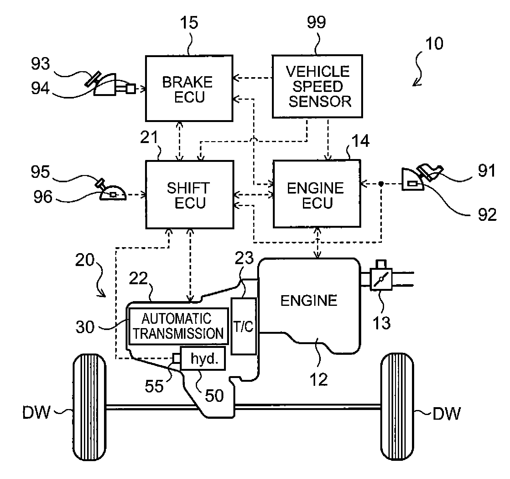
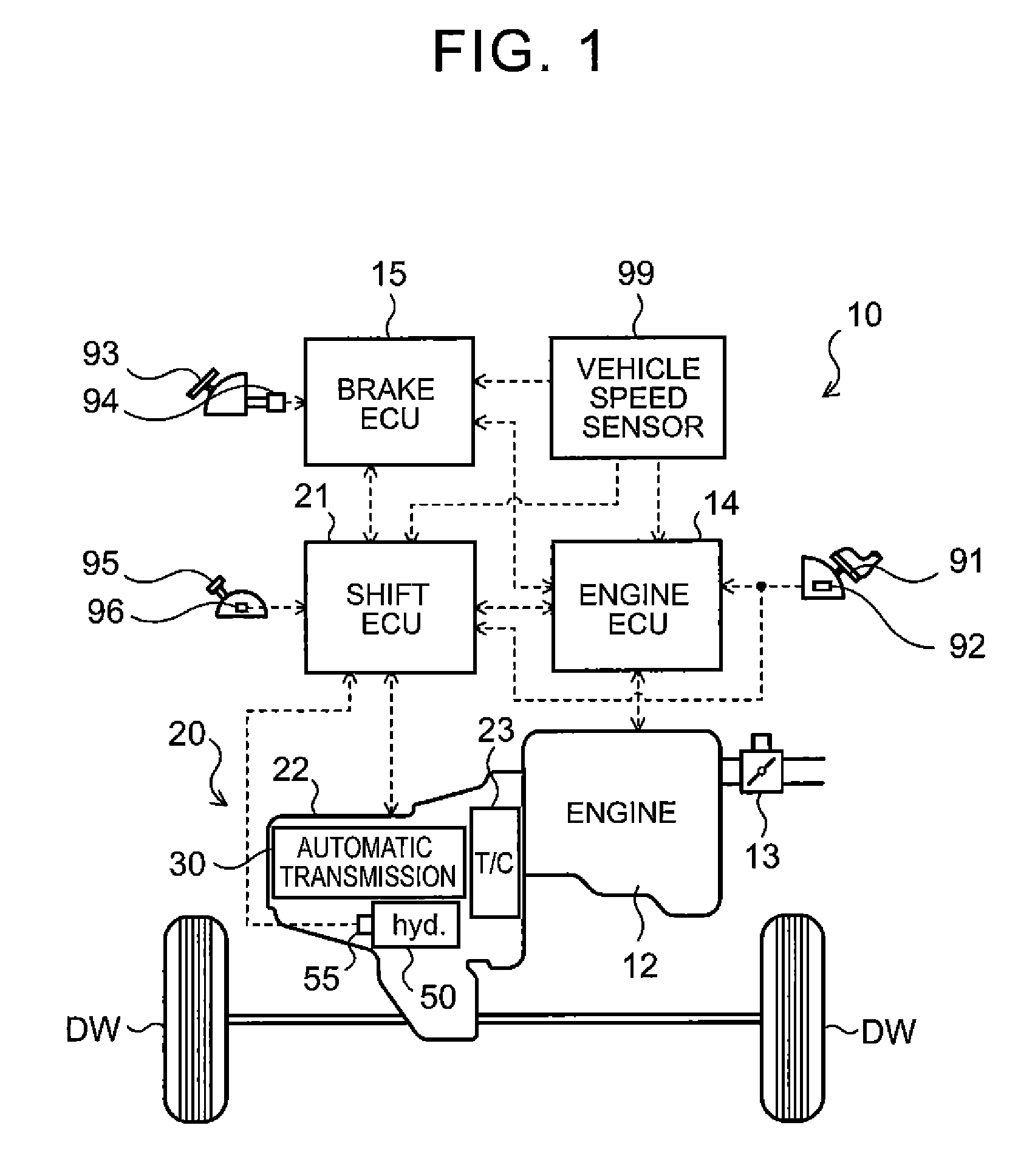
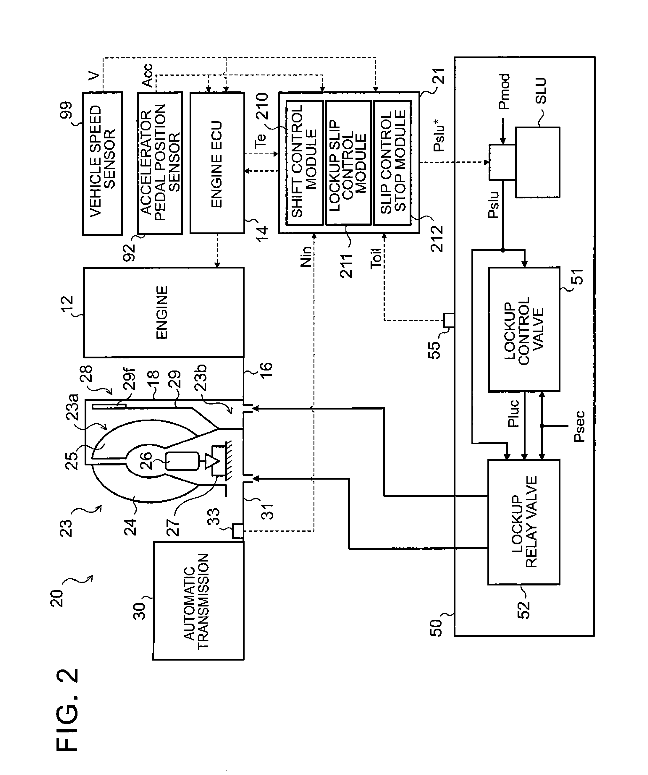
[0021]FIG. 1 is a schematic configuration diagram of an automobile 10 as a vehicle including a control device for a lockup clutch according to the present invention. The automobile 10 shown in the figure includes an engine (internal combustion engine) 12 as a motor that outputs power by explosive combustion of a mixture of air and hydrocarbon-based fuel such as gasoline or light oil, an engine electronic control unit (hereinafter referred to as the “engine ECU”) 14 that controls the engine 12, a brake electronic control unit (hereinafter referred to as the “brake ECU”) 15 that controls an electronically controlled hydraulic brake unit, not shown, a power transmission device 20 that is connected to the engine 12 and transmits power from the engine 12 to right and left drive wheels DW, etc. The power transmission device 20 has a transmission case 22, a hydraulic transmission device 23, a stepp...


PUM


Abstract

A control device for a lockup clutch of a vehicle. A slip control device executes slip control to make a rotational speed difference between the input member and the input shaft match a target slip speed according to a state of the vehicle by half engagement of the lockup clutch. A clutch temperature obtaining means obtains a clutch temperature of the lockup clutch. A determining means determines if the lockup clutch should be fully engaged or disengaged based on at least a state of the motor if the clutch temperature becomes equal to or higher than a predetermined temperature during execution of the slip control. A slip control stop means for stopping the slip control by fully engaging or disengaging the lockup clutch according to the determination result of the determining means.

Description

TECHNICAL FIELD[0001]The present invention relates to control devices and control methods for lockup clutches capable of coupling an input member connected to a motor of a vehicle and an input shaft of a transmission device and decoupling the input member and the input shaft.BACKGROUND ART[0002]Conventionally, a control device that prohibits slip control of a torque converter via slip engagement of a lockup clutch during a period from the time an estimate of a clutch facing temperature becomes equal to or higher than a slip control prohibition temperature to the time when the estimate of the clutch facing temperature becomes equal to or lower than a slip control permission temperature in order to prevent overheat is known as this type of control device for a lockup clutch (see, e.g., Patent Document 1). While the slip control is being prohibited, this control device causes the torque converter to function in a lockup state where front-rear differential rotation, namely a slip rotati...

Claims


Application Information

Patent Timeline
Patent Type & Authority Patents(United States)
IPC IPC(8): B60W10/00F16D43/20F16D43/25F16H61/14
CPCF16H61/14F16D43/25F16D43/20F16H2061/0425F16H61/143F16H2059/725
Inventor TSUTSUI, HIROSHIHASHIZUME, MAKOTO
Owner AISIN AW CO LTD
Why Eureka
Try Eureka