Drive control device, display device including the same, and drive control method

Inactive Publication Date: 2014-12-18
SHARP KK
View PDF6 Cites 17 Cited by
  • Summary
  • Abstract
  • Description
  • Claims
  • Application Information

AI Technical Summary

Benefits of technology

[0024]According to the first aspect of the present invention, the display device that performs low frequency drive performs, immediately after receiving image data from an external source during a pause period, an interrupt process where the pause period is allowed to transition to a charging period. Hence, without waiting for the pause period with a predetermined length to end, the next charging period starts. By this, a change to a screen according to the new image data can be performed more quickly than the conventional case. Therefore, a reduction in power consumption can be achieved while reducing screen change time.
[0025]According to the second aspect of the present invention, data transmission can be performed at high speed.
[0026]According to the third aspect of the present invention, an interrupt process can be

Problems solved by technology

Hence, in a display device using oxide TFTs as elements in a display panel, vo

Method used


Image

  • Drive control device, display device including the same, and drive control method
  • Drive control device, display device including the same, and drive control method
  • Drive control device, display device including the same, and drive control method

Examples


Example

1. First Embodiment

1.1 Overall Configuration and Summary of Operation

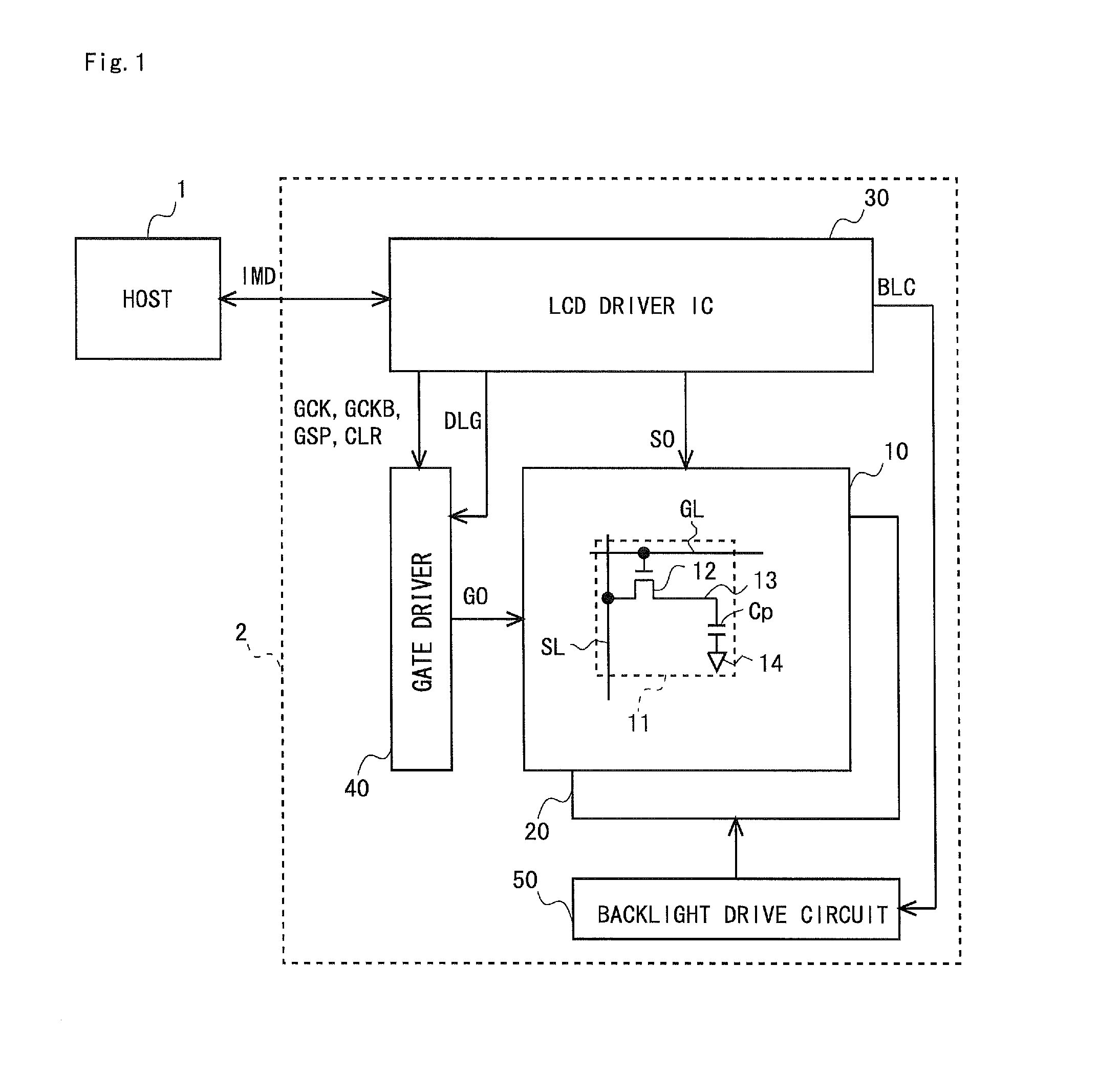
[0049]FIG. 1 is a block diagram showing a configuration of a liquid crystal display device 2 according to the first embodiment of the present invention. As shown in FIG. 1, the liquid crystal display device 2 includes a liquid crystal display panel 10, a backlight 20, an LCD driver IC 30 serving as a drive control device, a gate driver 40 serving as a scanning signal line driving unit, and a backlight drive circuit 50. The liquid crystal display device 2 is a liquid crystal display device that performs low frequency drive. A host 1 mainly composed of a CPU is provided outside the liquid crystal display device 2.

[0050]In the liquid crystal display panel 10, there are formed a plurality of source lines SL serving as video signal lines; a plurality of gate lines GL serving as scanning signal lines; and a plurality of pixel formation portions 11 provided at the respective intersections of the plurality of source lines ...

Example

2. Second Embodiment

2.1 Operation

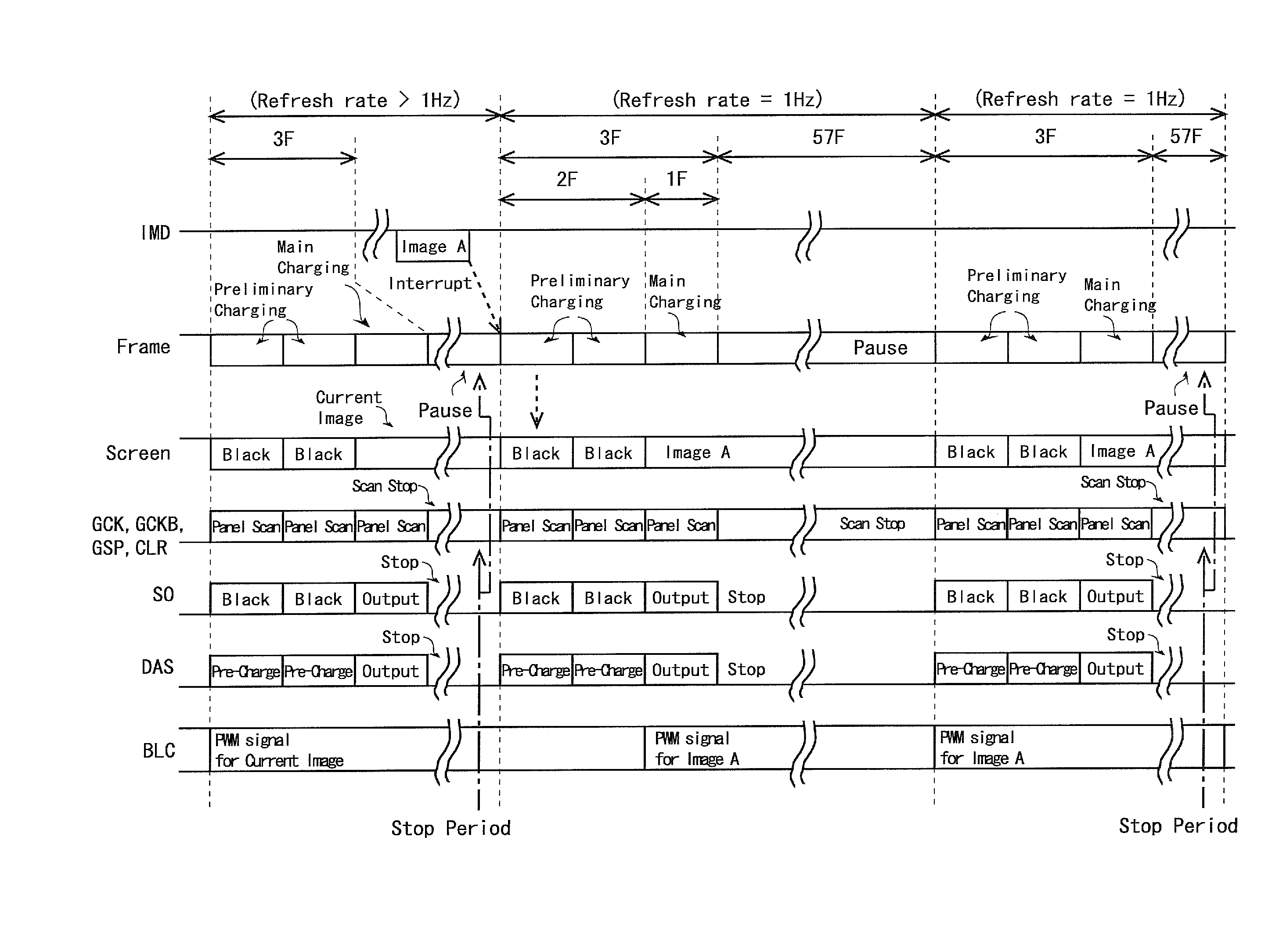
[0081]FIG. 7 is a diagram showing a drive control signal CT of the second embodiment of the present invention. Note that a liquid crystal display device 2 according to the present embodiment differs from that of the above-described first embodiment only in the operation thereof, and the components thereof are the same as those of the first embodiment. Hence, of the components of the present embodiment, the same components as those of the first embodiment are denoted by the same reference characters and description thereof is omitted where appropriate. As shown in FIG. 7, the drive control signal CT of the present embodiment goes to a high level for three frames immediately after a timing generator 312 receives a panel rendering start signal, and goes to a low level for 57 frames until receiving a panel rendering start signal next.

[0082]FIG. 8 is a timing chart for describing the operation of the liquid crystal display device 2 according to the presen...

Example

3. Third Embodiment

3.1 Operation

[0088]FIG. 10 is a timing chart for describing the operation of a liquid crystal display device 2 according to the third embodiment of the present invention and a host 1. Since the components of the present embodiment are the same as those of the first embodiment, the same components as those of the first embodiment are denoted by the same reference characters and description thereof is omitted where appropriate. In addition, since the operation of the liquid crystal display device 2 according to the present embodiment is the same as that in the second embodiment, except for operation related to a backlight control signal BLC, common description is omitted where appropriate. As shown in FIG. 10, in the present embodiment, as in the second embodiment, three frames are provided for a charging period, and 57 frames are provided for a pause period for when an interrupt process is not performed. Of the three frames, the first two frames are a preliminary c...


PUM


Abstract

Low frequency drive is performed that provides, after a charging period for refreshing a screen, a pause period for pausing the refresh. The length of the charging period is, for example, one frame and the length of the pause period is, for example, 59 frames. When new image data IMD is transmitted from a host to an LCD driver IC during the pause period, an interrupt process where the pause period is allowed to transition to the charging period is performed immediately thereafter. By performing the interrupt process, without waiting for the pause period with the predetermined length to end, the next charging period where refresh based on the new image data IMD is to be performed starts.

Description

TECHNICAL FIELD[0001]The present invention relates to a drive control device for a display device, and more particularly to a drive control device for a display device that performs low frequency drive, a display device including the drive control device, and a drive control method.BACKGROUND ART[0002]Conventionally, a reduction in power consumption is sought in display devices such as liquid crystal display devices. Hence, Japanese Patent Application Laid-Open No. 2001-312253 discloses a drive method for a display device, in which after a scanning period (also referred to as a charging period) T1 during which screen refresh is performed by scanning the gate lines of a liquid crystal display device, a pause period T2 during which the refresh is paused by placing all of the gate lines in a non-scanning state is provided. During the pause period T2, a gate driver is not provided with a clock signal and the like. Hence, since the overall drive frequency of the gate lines is reduced, a ...

Claims


Application Information

Patent Timeline
IPC IPC(8): G09G3/36G06F1/32
CPCG09G3/3618G09G3/3648G09G2330/021G06F1/325G09G2310/0251G09G3/3677G09G3/3611G09G2310/08G09G2330/022G09G2370/08G09G2370/10G09G3/3258
Inventor YOKONUMA, SHINSUKEWASHIO, HAJIME
Owner SHARP KK
Why Eureka
Try Eureka