Multi-station pipe end machining equipment

A processing equipment and multi-station technology, applied in the direction of metal processing equipment, metal processing, metal processing machinery parts, etc., can solve the problem that it is impossible to realize multiple manifolds to process pipe ends at the same time, and the requirements for automatic processing of pipe ends cannot be met. Problems such as low utilization rate can achieve the effect of improving equipment utilization rate, realizing assembly line operation and improving processing efficiency

Active Publication Date: 2012-09-26
ZHEJIANG MOTORBACS TECH
View PDF8 Cites 16 Cited by
  • Summary
  • Abstract
  • Description
  • Claims
  • Application Information

AI Technical Summary

Problems solved by technology

However, after the upper mold and the lower mold of the above-mentioned patent are combined, only one manifold can be clamped at a time, which cannot realize the requirement of processing pipe ends of multiple manifolds at the same time; moreover, the inner cavity formed by the upper mold and the lower mold can only be clamped. It can be applied to the shape of a manifold to be processed, and cannot process manifolds with different diameters and shapes. If you want to process manifolds of other shapes, you need to replace another equipment or replace the upper and lower molds. For automotive pipe fittings For manufacturers, manifolds of different specifications need to correspond to different pipe end processing equipment. The processing object of each equipment is single, the equipment utilization rate is low, and the investment cost is high. It cannot meet the requirements of efficient and economical pipe end automatic processing. To be further improved

Method used


Image

  • Multi-station pipe end machining equipment
  • Multi-station pipe end machining equipment
  • Multi-station pipe end machining equipment

Examples


Embodiment Construction

[0024] The present invention will be further described in detail below in conjunction with the accompanying drawings and embodiments.

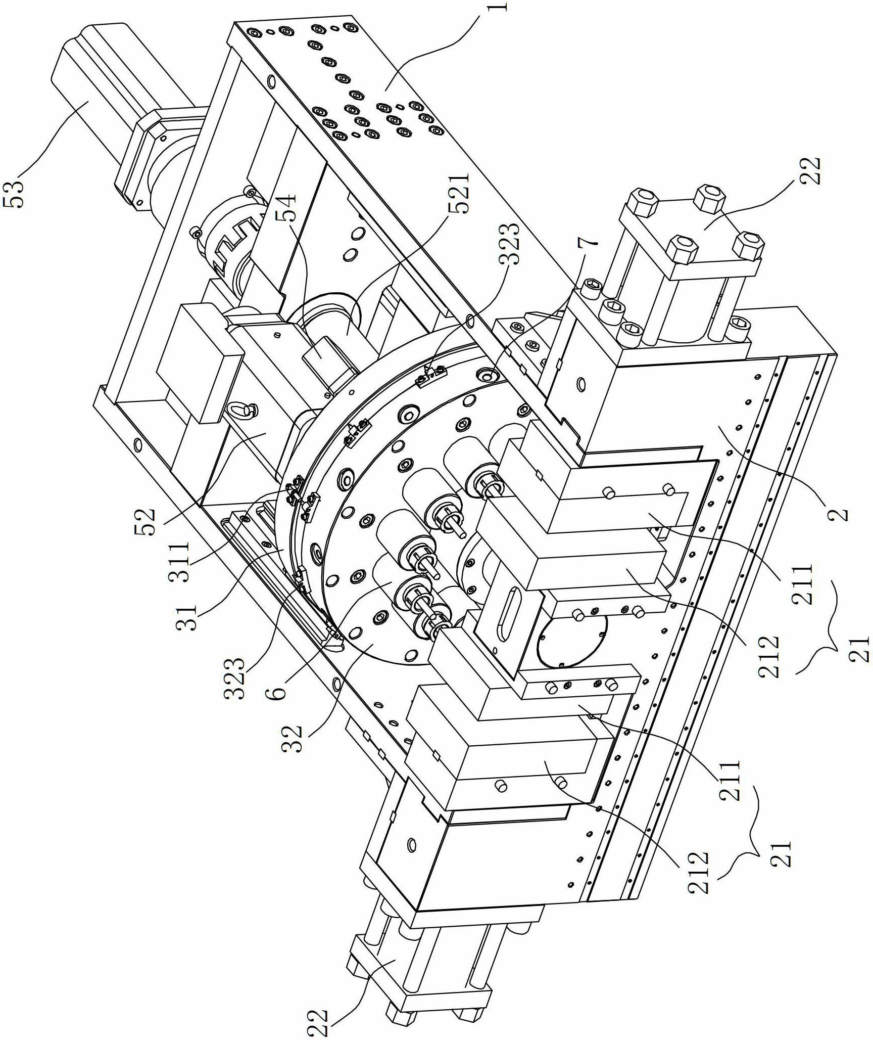
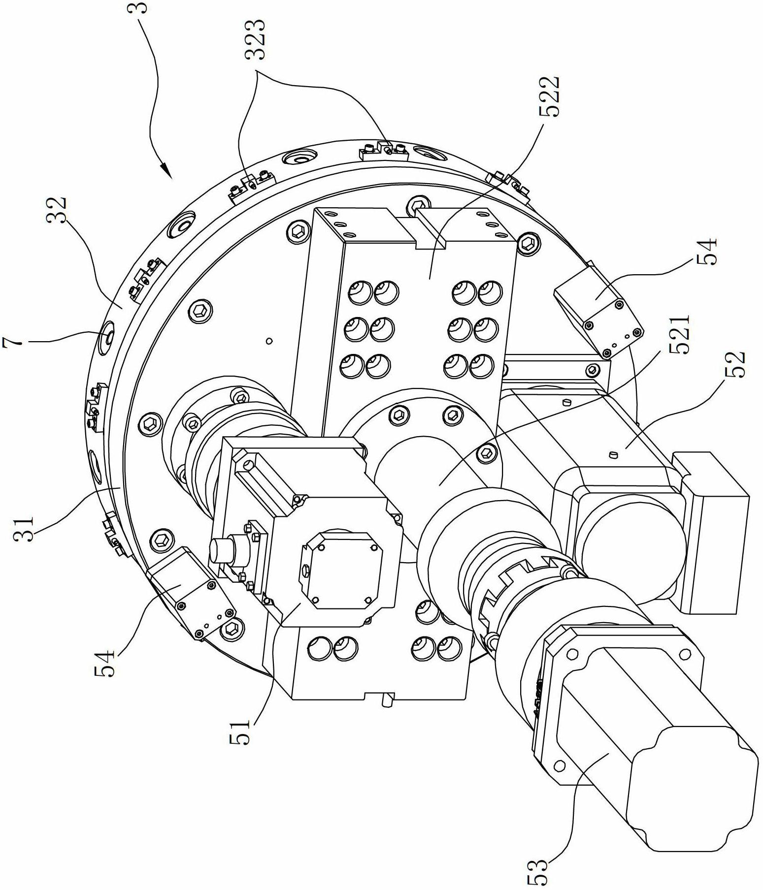
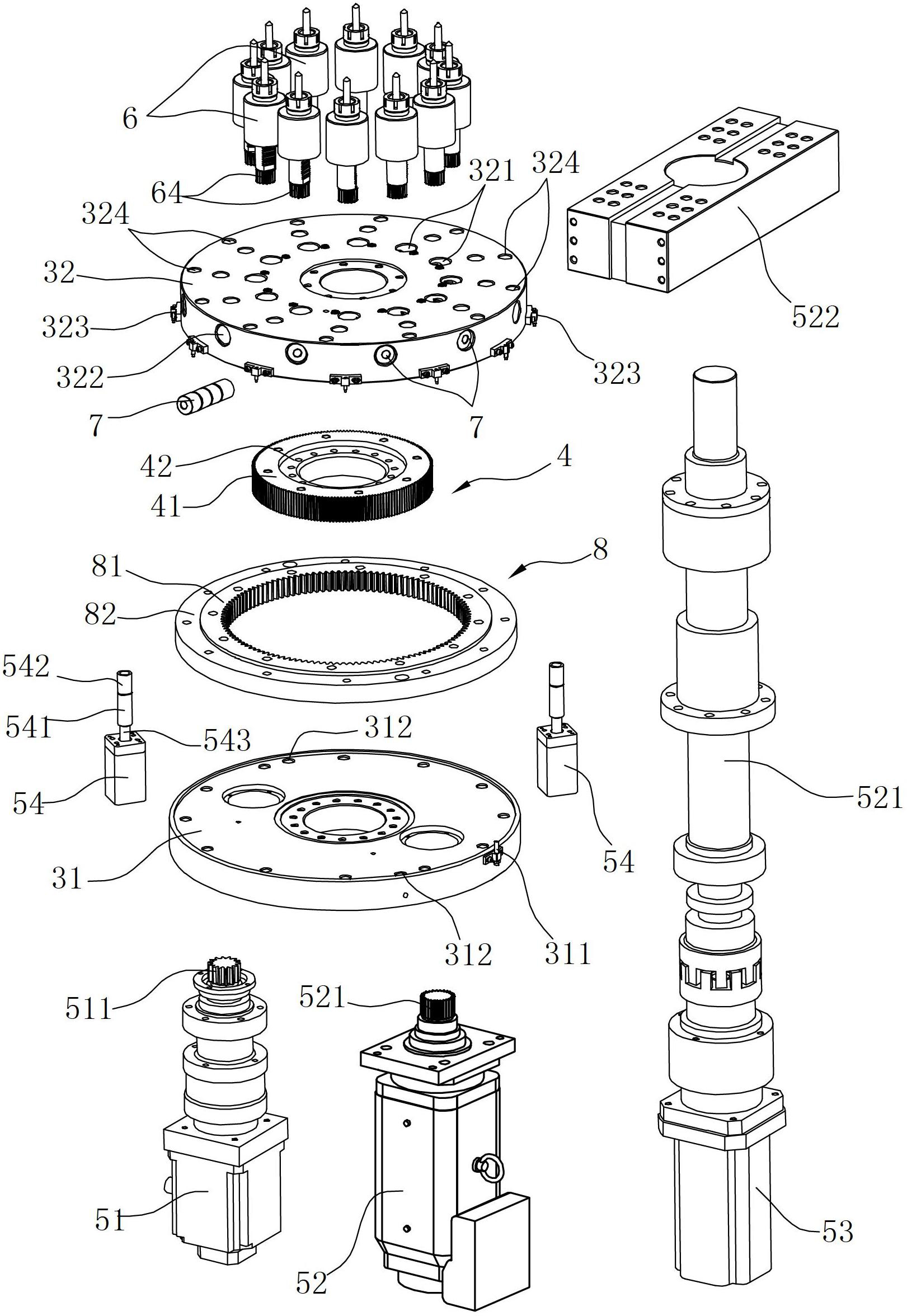
[0025] Such as Figure 1 to Figure 7 As shown, this embodiment is a multi-station pipe end processing equipment. The equipment adopts a turret tool 6, which can realize pipe end processing of special-shaped pipe fittings (such as automobile manifolds). The whole machine has a compact structure and high processing efficiency. high.

[0026]The multi-station pipe end processing equipment of this embodiment includes an organic base 1, a tool rest 3 installed on the base 1, and a pipe clamping device arranged directly in front of the tool rest 3, wherein the base 1 is semi-closed The U-shaped frame structure, the pipe clamping device is located at the U-shaped opening position of the machine base 1, the pipe clamping device includes a workbench 2 and two working positions arranged on the workbench 2 (it is also possible to increase the work numb...


PUM


Abstract

Multi-station pipe end machining equipment comprises a base and a cutter saddle, and is characterized in that the cutter saddle consists of a fixing plate and a cutter head, the fixing plate is vertically arranged, the cutter head is rotatably connected onto the fixing plate, a plurality of cutters are peripherally mounted on the cutter head, a pipe fitting clamping device is further disposed in front of the cutter saddle and comprises a worktable provided with at least two stations, a mold is arranged on each station and provided with a mold cavity, and a main driving device capable of driving the cutter saddle to linearly move towards or far away from the worktable is further disposed on the framework. Compared with the prior art, the multi-station pipe end machining equipment has the advantages that multiple cutters with different functions can be mounted at one step and can be changed only by rotating the cutter head, the trouble that the cutter needs to be changed for each machining procedure is avoided, cutter replacement time is saved, and machining efficiency is improved; and the worktable with the multiple stations is disposed at the front of the framework, multiple pipe fittings can be synchronously machined, utilization rate of the equipment is increased, and the requirement on integrated machining is met.

Description

technical field [0001] The invention relates to a pipe end processing equipment, in particular to a multi-station pipe end processing equipment for forming the pipe end of an automobile exhaust manifold. Background technique [0002] The automobile exhaust manifold is a special-shaped pipe structure with complex and diverse shapes. Its function is to make the exhaust gas vortex in the pipe, which can force the exhaust gas to be driven out and increase the exhaust speed. Due to the irregular shape of the exhaust manifold, the shapes of the nozzles at both ends of the exhaust manifold are usually different. The nozzle processing process of the traditional exhaust manifold generally requires multiple processes to complete, and each process needs to be completed once. Clamping is time-consuming and labor-intensive, and the processing accuracy and efficiency are low. [0003] In order to improve the nozzle processing efficiency of special-shaped pipe fittings, the existing Chine...

Claims


Application Information

Patent Timeline
Patent Type & Authority Applications(China)
IPC IPC(8): B23Q37/00B23B29/32B23Q7/00
CPCB23Q37/00B23Q7/00B23B29/32B23Q3/064B23Q5/10B23Q39/024B23Q39/044B23Q2039/006
Inventor 陆志伟陈军
Owner ZHEJIANG MOTORBACS TECH
Why Eureka
Try Eureka