[0004] However, none of the straight cylinder sewing machines currently on the market has a
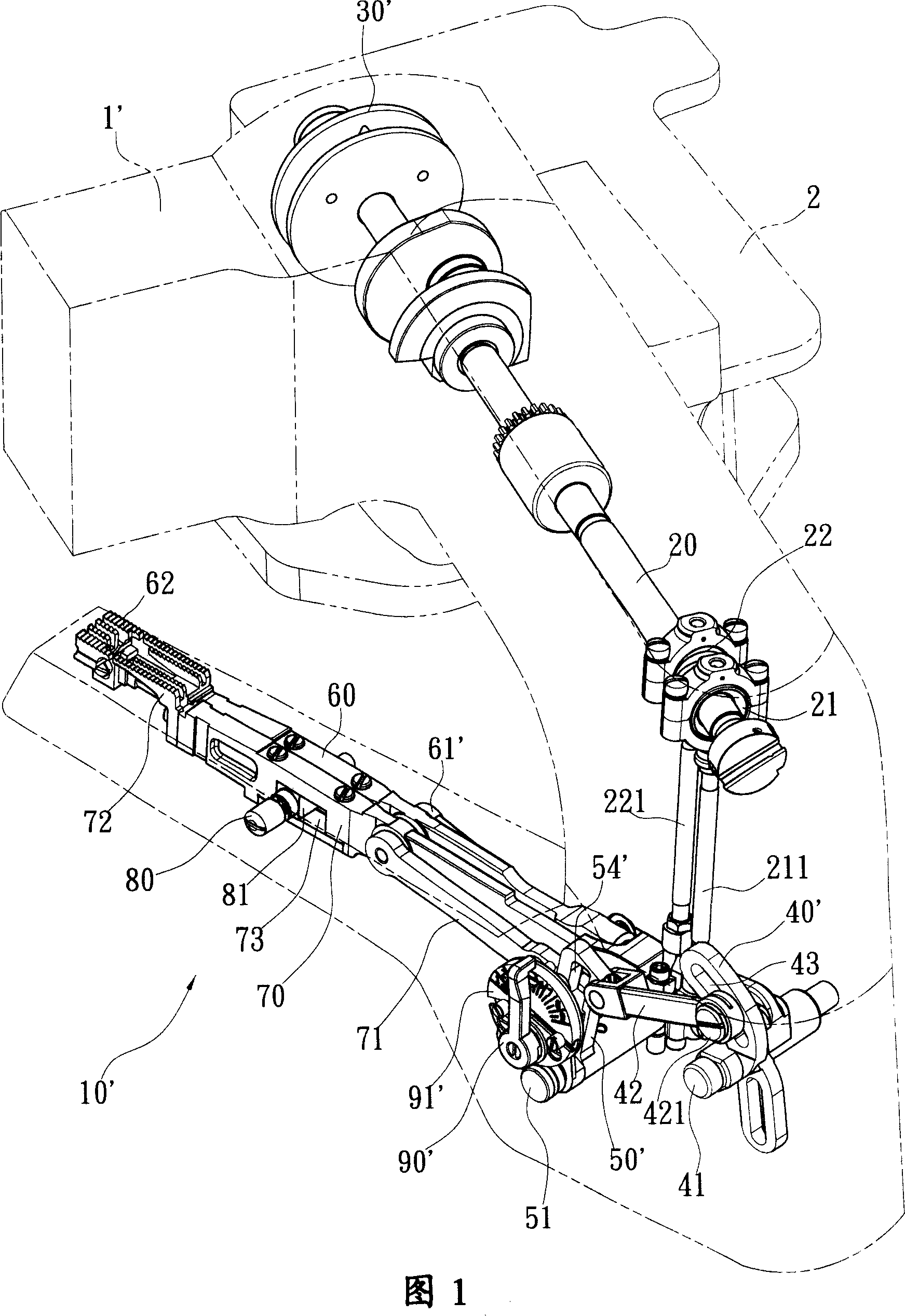
sewing machine that can separately control and adjust the travel distance of the front and rear two moving teeth (that is, the ratio of the thickness of the needle to the differential); figure 1 and figure 2 As shown, the main feed mechanism 10' of the known straight cylinder sewing
machine 1' utilizes a
drive shaft 20 to transmit the rotational power source, and the
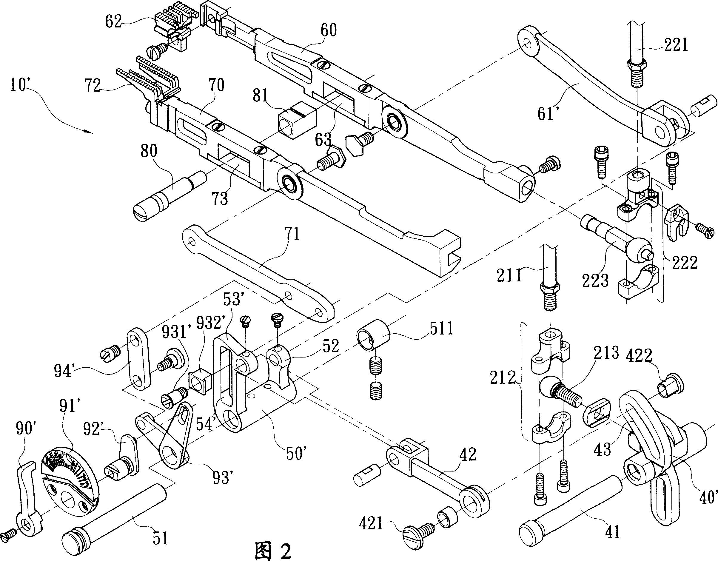
drive shaft 20 is provided with a first eccentric shaft 21 and a second eccentric shaft 22, and the first eccentric shaft 21 is pivotally connected with the first lifting rod 211, and the second eccentric shaft 22 is pivotally connected with the second lifting rod 221, wherein the second ball seat 222 below the second lifting rod 221 is pivotally connected A second ball connecting rod 223, the second ball connecting rod 223 is directly connected with a front moving gear linkage rod 60, so when the transmission main shaft 20 continues to rotate, the second elevating rod 221 will move up and down , so that the front moving tooth link rod 60 can move up and down, and because the rear moving tooth link bar 70 is abutted on the front moving tooth link bar 60, it can move up and down synchronously with the front moving tooth link bar 60 ; In addition, the first ball seat 212 below the first lifting rod 211 is pivotally connected to a first ball connecting rod 213, and the first ball connecting rod 213 is fixed on a pivot driving member 40', and the pivot driving Part 40' is set on a driving part fixed shaft 41, so when the driving wheel 30' receives continuous power to rotate, the transmission main shaft 20 will continue to rotate, and the first elevating rod 211 will move up and down, so that the shaft Turn the driving member 40' to swing; in addition, because the shaft rotating driving member 40' is pivoted to a biaxial transduction rod 42, and the biaxial transduction rod 42 is in turn connected to a rocking member 50', so the rocking member 50 can ' rock back and forth on the rocker fixed shaft 51, and because there is a front moving tooth rocker 52 and a rear moving tooth rocker 53' on the rocker 50', and there is a limit on the rear moving tooth rocker 53'. Position guide groove 54', there is a limit slider 932' that can slide and displace on the limit guide groove 54', the limit slider 932' is connected with a limit shaft 931 ' shaft connection, and the limit shaft 931' is fixedly connected to a rear moving tooth push-pull rod 71, and the rear moving tooth push-pull rod 71 is connected to a rear moving tooth linkage rod 70, so when the rocker 50' When rocking back and forth, then can drive this rear mobile tooth
interlocking rod 70 horizontal displacement back and forth; This front mobile tooth rocker 52 is to be connected with a front mobile tooth push-pull bar 61 ' axis in addition, and this front mobile tooth push-pull bar 61 ' is connected with again A front moving tooth linkage rod 60 is pivotally connected, so when the rocker 50' rocks back and forth, it can drive the front movement tooth linkage lever 60 to move horizontally back and forth; 53' on the rocker fixed shaft 51 on one side, the shaft is provided with a torque type shaft pull lever 93 ', one end of the torque type shaft pull lever 93 ', the shaft is connected to one end of a push-pull
brake lever 94', and the push-pull The other end of the
brake lever 94' is axially connected with the middle section of the rear moving tooth push-pull rod 71. Since the other end of the torque type shaft pull lever 93' is provided with a linkage shaft pull lever 92', the linkage shaft pull lever 92' 92' passes through a dial 91' and is fixedly connected with a moving tooth adjusting lever 90', so when the moving tooth adjusting lever 90' is pulled, the torque shaft lever 93' will be driven at the same time At this time, the push-pull
brake lever 94' that is connected to the torque-type shaft lever 93' at one end is affected and drags the rear-moving tooth push-pull rod 71, while the limit shaft connected to the limit shaft 931' Slider 932', because the limit shaft 931' is fixedly connected to one end of the rear moving tooth push-pull rod 71, it will slide and displace in the limit guide groove 54', and because the rocker 50' is shaken The movement of the rear moving tooth push-pull rod 71 is driven, so the position of the limit shaft 931' affixed to the rear mobile tooth push-pull rod 71 in the position-limiting guide groove 54' will affect the position of the rear mobile tooth push-pull rod 71'. The size of the movement of the pull rod 71 ultimately affects the displacement
stroke distance of the rear moving tooth 72 located at the end of the rear moving tooth linkage rod 70; in addition, since a limiting guide groove 43 is also provided on the shaft-rotating driving member 40', and The biaxial transfer guide rod 42 is axially connected to the limit guide groove 43, so when the displacement
stroke distance of the front moving tooth 62 is to be changed, the biaxial transfer guide rod 42 can be pivoted to the limit guide groove 43. The connected feed adjustment bolt 421 is loosened, moved to other positions and then locked. Since the movement of the biaxial transduction rod 42 is generated by the swing of the shaft rotation drive member 40', the biaxial transduction rod 42 The position of the feed adjustment bolt 421 axially connected with the limiting guide groove 43 will affect the shaking size of the shaking member 50 ′, and finally affect the displacement
stroke distance of the front moving tooth 62 and the rear moving tooth 72


