Display supporting mechanism

A technology of display and force-applying parts, applied in the direction of instruments, instrument parts, identification devices, etc., can solve the problem that the display cannot rotate smoothly

Inactive Publication Date: 2008-01-02
KATOH ELECTRIC MACHINERY
View PDF1 Cites 6 Cited by
  • Summary
  • Abstract
  • Description
  • Claims
  • Application Information

AI Technical Summary

Problems solved by technology

Therefore, when the display is rotated in an oblique direction about the axis, a force greater than a large frictional torque is required, and there is a problem that the display cannot be rotated smoothly.

Method used


Image

  • Display supporting mechanism
  • Display supporting mechanism
  • Display supporting mechanism

Examples


Embodiment Construction

[0019] An example of the display support mechanism of the present invention will be described in detail below with reference to the accompanying drawings.

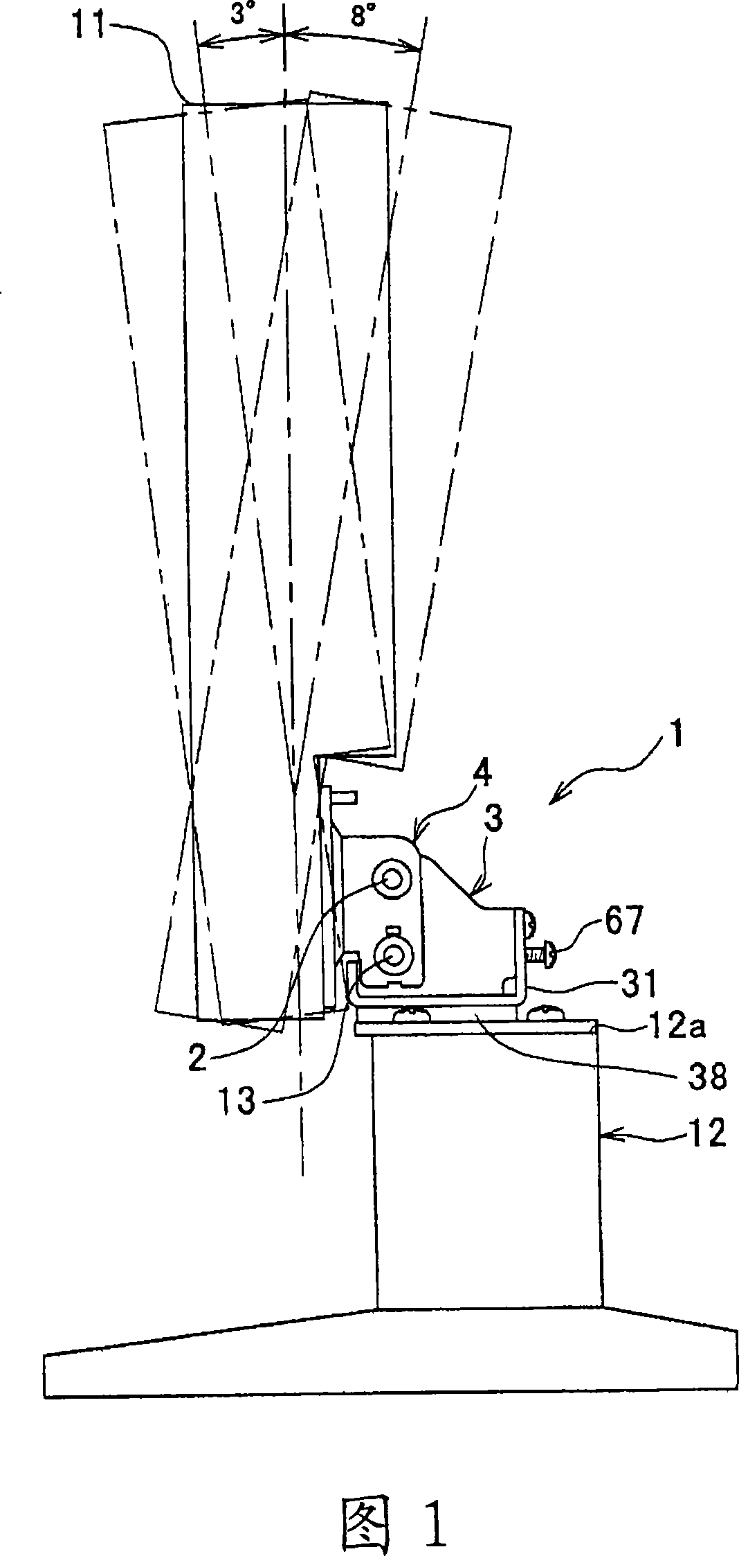
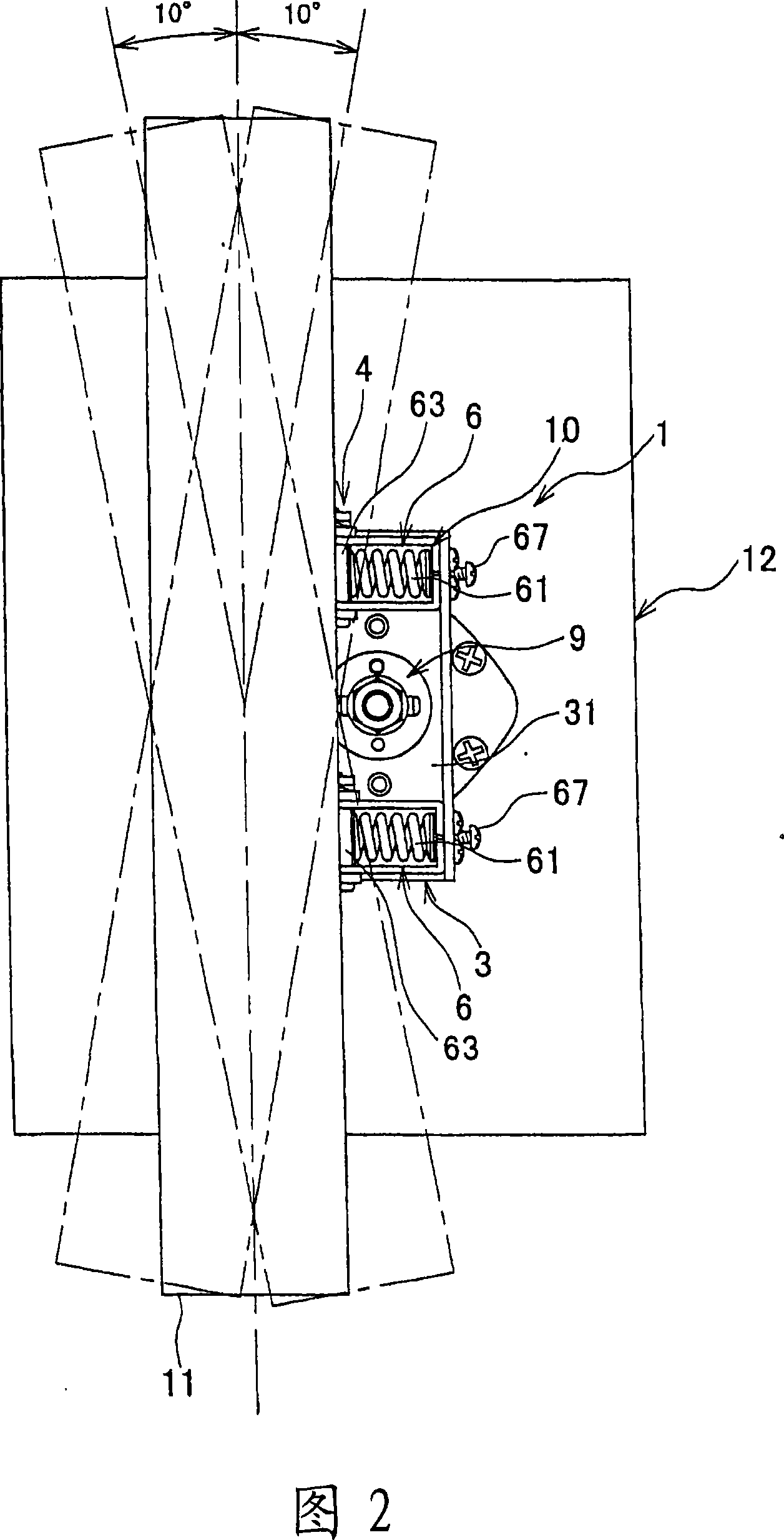
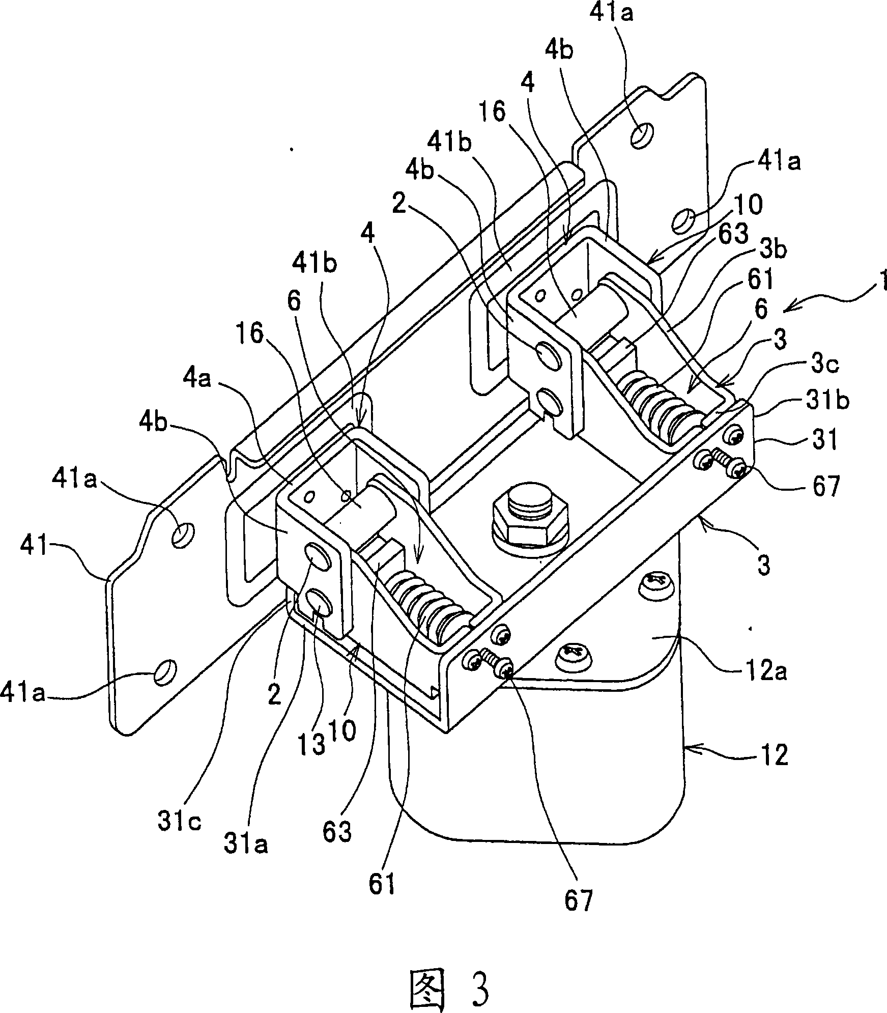
[0020] 1 to 8 are diagrams showing an example of a display support mechanism of the present invention. As shown in FIGS. 1 to 8 , the display support mechanism of the present invention is a mechanism for tilting the display 11 in a tilting direction with respect to the base portion 12 . The display 11 is a fixed display such as a monitor or a liquid crystal television, and the display supporting mechanism of the present invention is particularly practical for a large monitor and a liquid crystal television. The display 11 is supported on a base portion 12 and placed on a TV table or the like via the base portion 12 . The display support mechanism 1 of the present invention is a support mechanism that connects the display 11 and the base portion 12 .

[0021] The display support mechanism 1 of the present invention is cha...


PUM


Abstract

The invention provides a display support mechanism for swimmingly rotating the display. The display support mechanism slantwise moves the display along vergence direction according to the base station, and comprises: axis; first bracket, which is rotationably located on the axis, and is fixed on one of back surface of the display and the base station; second bracket, which is rotationably located on the axis, and is fixed on the other of back surface of the display and the base station; friction force production unit, which produces friction force between the first bracket and the second bracket to keep the display on the preconcerted position of the base station; and falling torque elimination unit, which is located between the back surface of the display and the base station, and eliminates force forward along the axis of the display.

Description

technical field [0001] The present invention relates to a display support mechanism for stopping fixed displays such as monitors and liquid crystal televisions at desired positions by frictional force. Background technique [0002] Stationary displays such as monitors and liquid crystal televisions are supported on a base portion, and are placed on a TV table or the like through the base portion. The display and the base are connected by a display support mechanism. The display support mechanism supports the display so as to be able to tilt and move relative to the base portion. As a display support mechanism, a support mechanism having a pair of left and right friction hinges is known (for example, refer to Patent Document 1). The friction hinge is left-right symmetrical about the base part as an axis. Shafts are extended in the left-right direction on the base part, and the bracket is rotatably attached to these shafts. These stands are attached to the monitor, and the...

Claims


Application Information

Patent Timeline
Patent Type & Authority Applications(China)
IPC IPC(8): G12B9/08G12B3/08G09F9/00
Inventor 反町亮
Owner KATOH ELECTRIC MACHINERY
Why Eureka
Try Eureka