Substrate treating apparatus

一种基板处理装置、处理位置的技术,应用在电气元件、半导体/固态器件制造、电路等方向,能够解决残渣、不能清洁干净地干燥基板等问题,达到提高生产率的效果

Active Publication Date: 2008-01-02
DAINIPPON SCREEN MTG CO LTD
View PDF1 Cites 1 Cited by
  • Summary
  • Abstract
  • Description
  • Claims
  • Application Information

AI Technical Summary

Problems solved by technology

However, if the pressure is applied in this way, the vapor of isopropanol in the processing chamber condenses and forms droplets that adhere to the substrate, resulting in residues.
Therefore, the substrate cannot be dried cleanly

Method used


Image

  • Substrate treating apparatus
  • Substrate treating apparatus
  • Substrate treating apparatus

Examples


Embodiment 1

[0022] Hereinafter, Embodiment 1 of the present invention will be described with reference to the drawings.

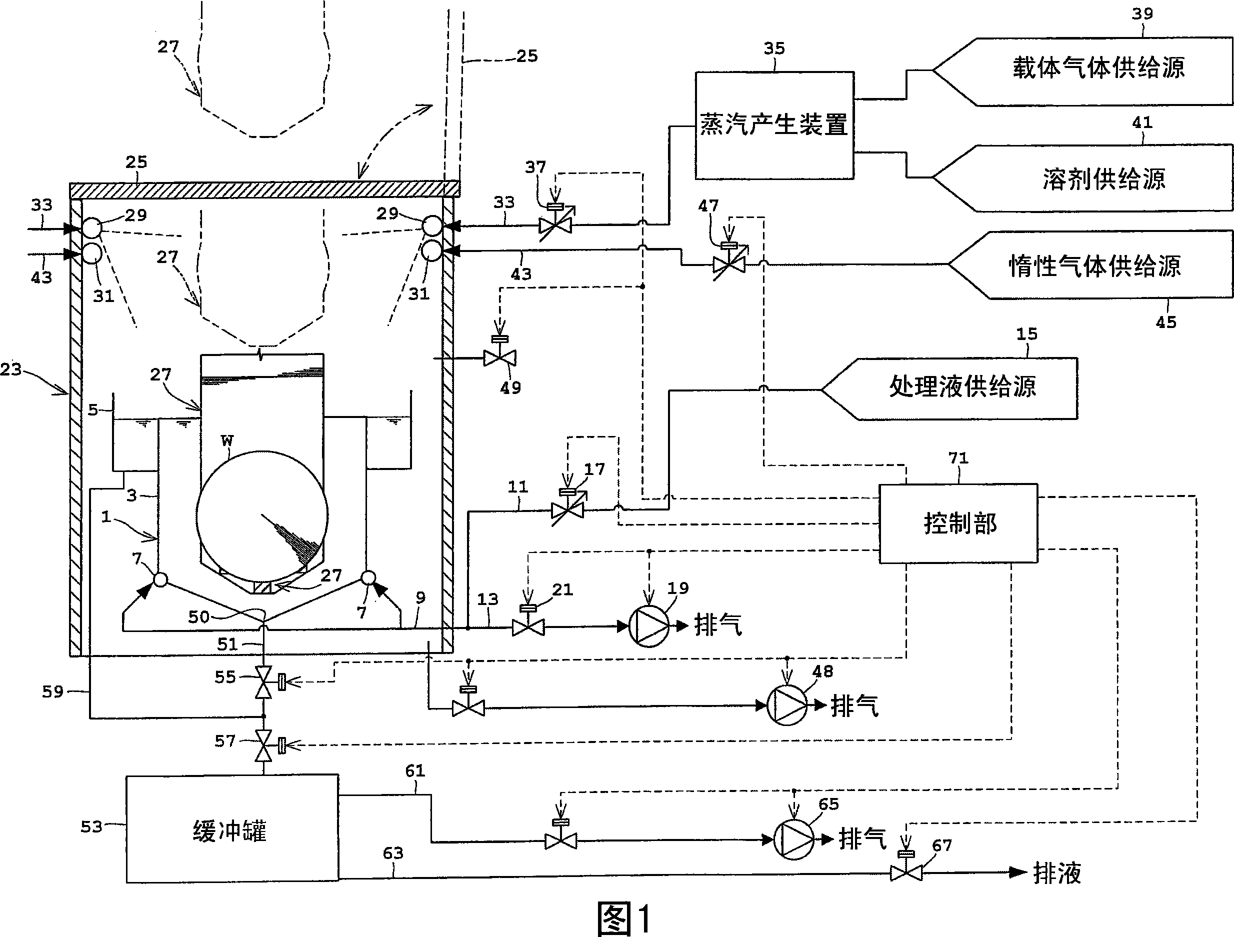
[0023] FIG. 1 is a schematic configuration diagram of a substrate processing apparatus according to the first embodiment.

[0024] The substrate processing apparatus of this embodiment has a processing tank 1 that stores a processing liquid. The processing tank 1 has an inner tank 3 that stores a processing liquid and accommodates a substrate W, and an outer tank 5 that collects the processing liquid overflowing from the inner tank 3 . Two injection pipes 7 for supplying the treatment liquid into the inner tank 3 are arranged at the bottom of the inner tank 3 , and a pipe 9 is connected to the injection pipes 7 . The piping 9 is branched into a supply pipe 11 and a suction pipe 13 . The supply pipe 11 is connected to a processing liquid supply source 15, and the flow rate thereof is controlled by a processing liquid valve 17 constituted by a control valve. The sucti...

Embodiment 2

[0047] Embodiment 2 of the present invention will be described below with reference to the drawings.

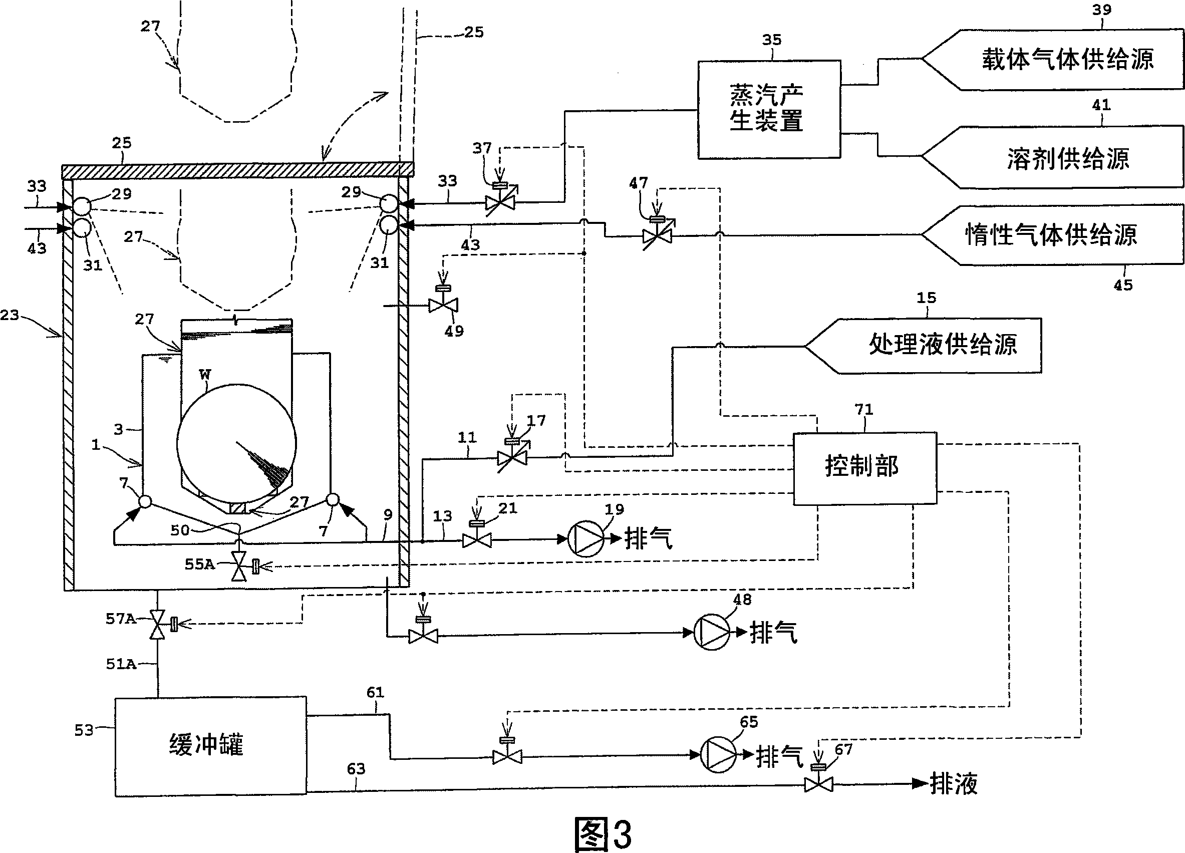
[0048] FIG. 3 is a schematic configuration diagram of a substrate processing apparatus according to the second embodiment, and the same configurations as those of the first embodiment described above are denoted by the same reference numerals, so detailed description thereof will be omitted.

[0049] The differences between the substrate processing apparatus of the second embodiment and the configuration of the first embodiment described above are as follows.

[0050] That is, the processing tank 1 only has the inner tank 3 without the outer tank 5; the QDR valve 55A is arranged at the discharge port 50 of the inner tank 3, and when the liquid is discharged from the QDR valve 55A, the processing liquid in the inner tank 3 is temporarily discharged into the processing chamber In room 23. A discharge pipe 51A communicating with the buffer tank 53 is installed at the bottom of ...


PUM


Abstract

A substrate treating apparatus for drying substrates by moving the substrates out of a treating liquid into a solvent atmosphere. The apparatus includes a treating tank for storing the treating liquid, a chamber enclosing the treating tank, a holding mechanism for holding the substrates, the holding mechanism being vertically movable between a treating position in the treating tank and a drying position in the chamber and above the treating tank, a supply device for supplying vapor of a solvent into the chamber, a buffer tank disposed outside the chamber for collecting the treating liquid discharged from the treating tank, a first vacuum pump for decompressing the chamber, a second vacuum pump for decompressing the buffer tank, and a controller for operating the supply device to fill the chamber with the solvent atmosphere, operating the holding mechanism to move the substrates from the treating position to the drying position, operating the first vacuum pump to decompress the chamber to a first pressure, and operating the second vacuum pump to adjust a pressure in the buffer tank to a second pressure equal to or lower than the first pressure before the treating liquid in the treating tank is discharged into the buffer tank.

Description

technical field [0001] The present invention relates to a substrate processing apparatus for drying substrates such as semiconductor wafers or glass substrates for liquid crystal display devices (hereinafter simply referred to as substrates), and in particular to drying substrates in a state where a processing chamber in a solvent environment is decompressed. A technology that moves from a processing liquid to a solvent environment for drying. Background technique [0002] Conventionally, such an apparatus includes a processing tank for storing pure water, a processing chamber surrounding the processing tank, a holding mechanism for raising and lowering the substrate between a processing position in the processing tank and a drying position above the processing tank, In the treatment chamber, there is a nozzle for supplying isopropanol vapor (IPA), a vacuum pump for depressurizing the treatment chamber, and a treatment device for a discharge pipe that discharges pure water f...

Claims


Application Information

Patent Timeline
Patent Type & Authority Applications(China)
IPC IPC(8): H01L21/00H01L21/67
CPCH01L21/67028H01L21/67034Y10S134/902H01L21/02H01L21/304
Inventor 相原友明
Owner DAINIPPON SCREEN MTG CO LTD
Why Eureka
Try Eureka