Wire insulating paint efficient-clearing device

A wire insulation and removal device technology, applied in the directions of dry gas arrangement, cleaning methods and utensils, cleaning methods using tools, etc., can solve the problems of incomplete reaction, low work efficiency, poor effect of insulating paint treatment, etc. Work efficiency, easy to use, clean effect

Inactive Publication Date: 2019-02-01
FUJIAN NANAN XIAMEI ELECTRONICS EQUIP FACTORY
View PDF17 Cites 2 Cited by
  • Summary
  • Abstract
  • Description
  • Claims
  • Application Information

AI Technical Summary

Problems solved by technology

[0004] The currently announced Chinese patent authorization announcement number is CN205550973U, a kind of wire insulating varnish quick removal device, although the insulating varnish on the surface of the wire can be processed, but the equipment is attached to the wire due to the insulating varnish in the process of chemical reaction, so itself Chemical reaction with the solution will result in long reaction time, low work efficiency, and incomplete reaction, which will lead to poor effect of insulating varnish on the surface of the wire

Method used


Image

  • Wire insulating paint efficient-clearing device
  • Wire insulating paint efficient-clearing device
  • Wire insulating paint efficient-clearing device

Examples


Embodiment 1

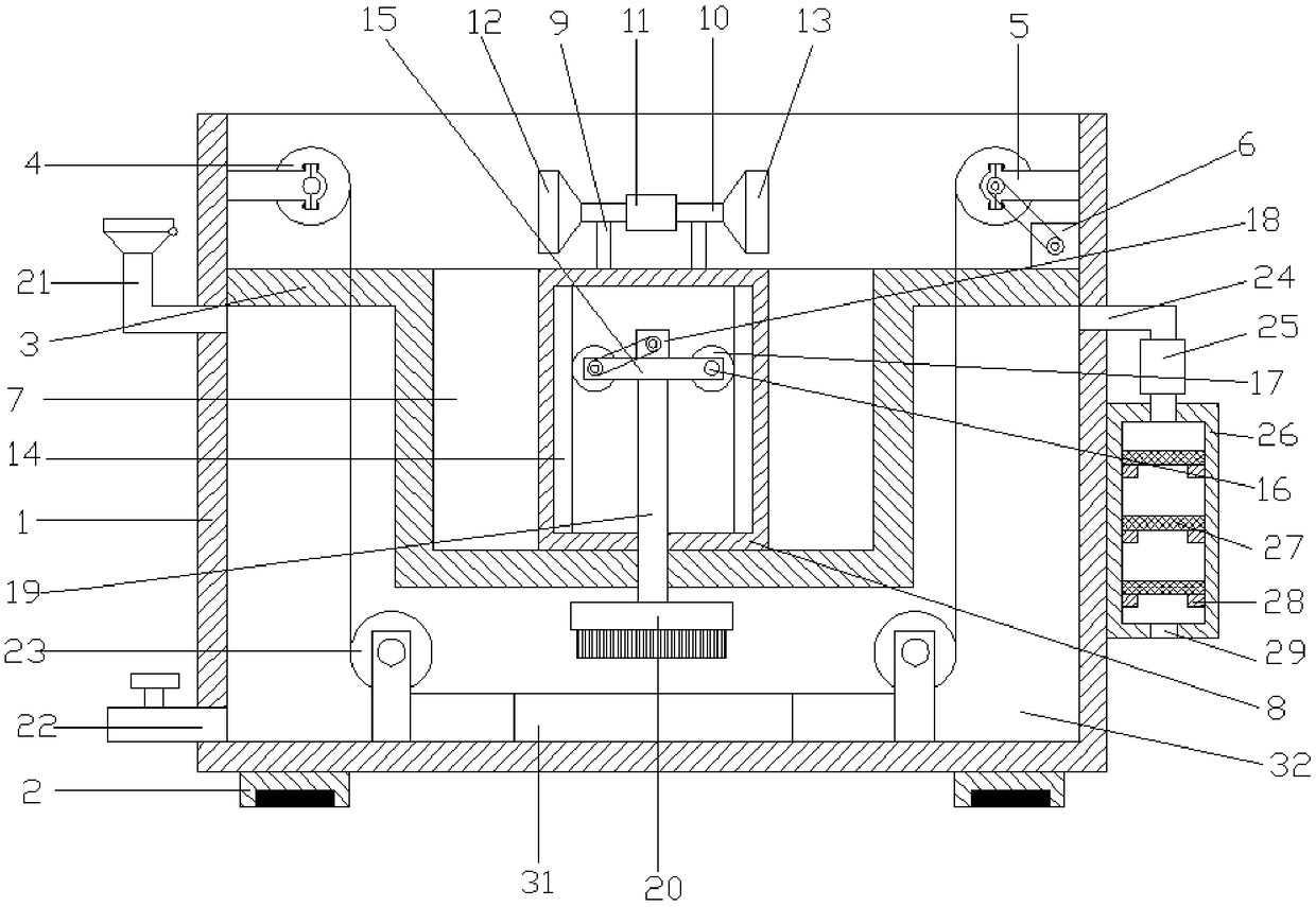
[0025] refer to Figure 1~3 , in the embodiment of the present invention, a high-efficiency removal device for wire insulation varnish, including a box body 1, a support seat 2 is welded at the four corners of the lower side of the box body 1, and a friction pad is inlaid at the inner lower end of the support seat 2, which can effectively Increase the friction between the equipment and the ground, which can effectively ensure the stability of the equipment. The upper end of the box body 1 is provided with a partition 3, and the lower side of the partition 3 is a cleaning chamber 32. The partition 3 A pay-off roller 4 is installed on the left end of the upper side, which can be used for winding wires with insulating varnish. A take-up roller 5 is installed on the right end of the upper side of the partition 3, and a first motor is arranged on the lower side of the take-up roller 5 6. The first motor 6 is connected to the shaft of the take-up roller 5 through a belt, and the fir...

Embodiment 2

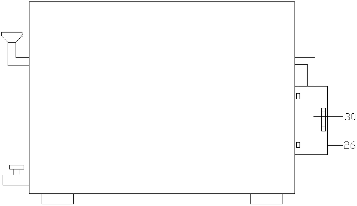
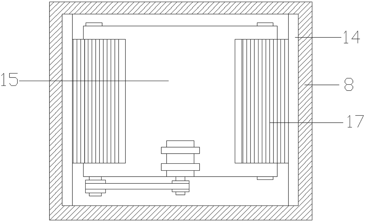
[0028]The difference from Embodiment 1 is that: the upper end of the right side of the box body 1 is provided with a suction pipe 24, the suction pipe 24 is equipped with a suction pump 25, and the lower side of the suction pipe 24 is connected with a purification chamber 26, The clean chamber 26 is fixed on the right side of the box body 1, and the inside of the clean chamber 26 is provided with several activated carbon adsorption plates 27, and the left and right ends of the activated carbon adsorption plate 27 are welded with baffles 28. The lower side of 26 is provided with an air outlet 29, which can effectively absorb the waste gas produced by the chemical reaction between the insulating varnish and the solution, which can effectively protect the cleanliness of the working environment. The front side of the purification chamber 26 is connected by a hinge There is a chamber door 30, which can facilitate the replacement of the active carbon adsorption plate 27.


PUM


Abstract

The invention relates to the field of unmanned aerial vehicles, in particular to a wire insulating paint efficient-clearing device which comprises a box body, wherein a partition plate is arranged atthe upper end of the interior of the box body; a cleaning cavity is positioned on the lower side of the partition plate; a pay-off roll is mounted at the left end of the upper side of the partition plate; a take-up roll is mounted at the right end of the upper side of the partition plate; a groove is formed in the middle of the partition plate; a connecting hood is mounted inside the groove through a bolt; supporting rods are welded to the left and right ends of the upper side of the connecting hood; gear racks are arranged at the left and right ends of the interior of the connecting hood; a connecting plate is arranged at the upper end of the clearance between the gear racks; the left and right sides of the connecting plate are connected with gears through connecting shafts; a connectingpipe is welded to the lower side of the connecting plate; a brush is welded to the lower side of the connecting pipe and arranged at the lower end of the interior of the cleaning cavity; a baseplate is fixedly mounted at the bottom of the cleaning cavity and positioned below the brush; and limiting plates are arranged on the left and right sides of the baseplate. By the adoption of the wire insulating paint efficient-clearing device provided by the invention, the effective and convenient disposal of insulating paint on a wire can be achieved, thereby improving the working efficiency of the wire insulating paint efficient-clearing device and facilitating the use of the wire insulating paint efficient-clearing device.

Description

technical field [0001] The invention relates to the field of unmanned aerial vehicle production, in particular to a high-efficiency removal device for wire insulating varnish. Background technique [0002] Unmanned aircraft, referred to as "unmanned aerial vehicle", or "UAV" in English, is an unmanned aircraft that is controlled by radio remote control equipment and its own program control device, or is completely or intermittently operated autonomously by an on-board computer. [0003] Drones are often better suited for missions that are too "dumb, dirty or dangerous" than manned aircraft. According to the application field, UAV can be divided into military and civilian. In terms of military use, UAVs are divided into reconnaissance aircraft and target aircraft. In terms of civilian use, drones + industry applications are the real rigid needs of drones; currently, they are used in aerial photography, agriculture, plant protection, micro selfies, express delivery, disaster...

Claims


Application Information

Patent Timeline
IPC IPC(8): B08B3/08B08B1/02F26B21/00
CPCF26B21/004B08B3/041B08B3/08B08B1/12B08B1/20
Inventor 傅亚蓉
Owner FUJIAN NANAN XIAMEI ELECTRONICS EQUIP FACTORY
Why Eureka
Try Eureka