Terminalless communication cable distribution box and its connection method

A communication cable and transfer box technology, applied in the field of communication, can solve problems such as difficulty, oxidation of the connecting end cable, damage and replacement of the connecting module, etc., and achieve the effects of easy operation, quality assurance, and oxidation prevention.

Inactive Publication Date: 2008-01-02
昆山市大唐通讯设备有限公司
View PDF1 Cites 0 Cited by
  • Summary
  • Abstract
  • Description
  • Claims
  • Application Information

AI Technical Summary

Problems solved by technology

[0003] The purpose of the present invention is to overcome the defects of the prior art, and propose a terminalless communication cable transfer box to increase the service life of the splicing module, solve the problem of oxidation of the splicing end cables, and solve the problem of difficult replacement due to damage to a certain splicing end of the splicing module problem, solve the problem of special cable splicing

Method used


Image

  • Terminalless communication cable distribution box and its connection method
  • Terminalless communication cable distribution box and its connection method
  • Terminalless communication cable distribution box and its connection method

Examples


Embodiment Construction

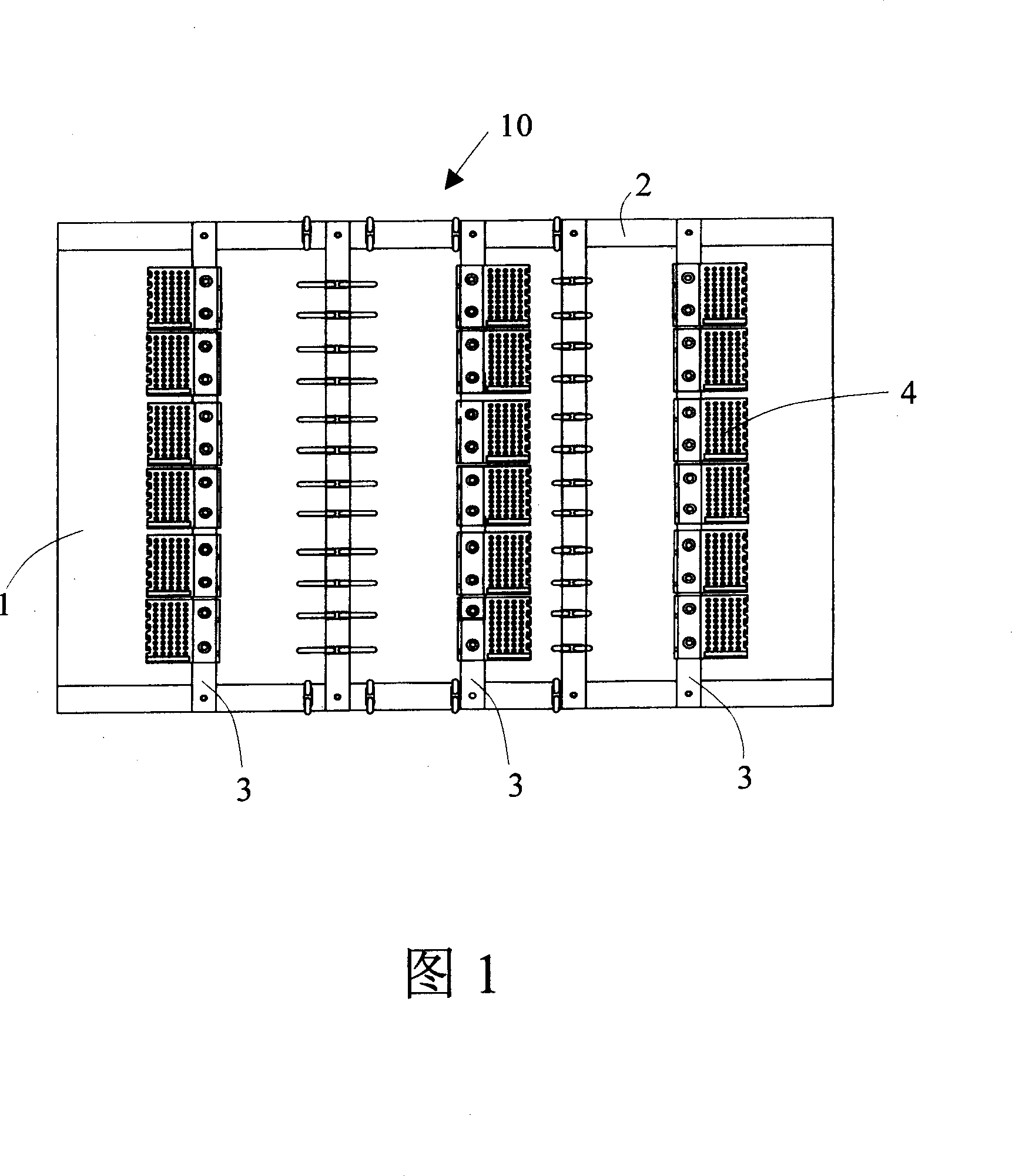
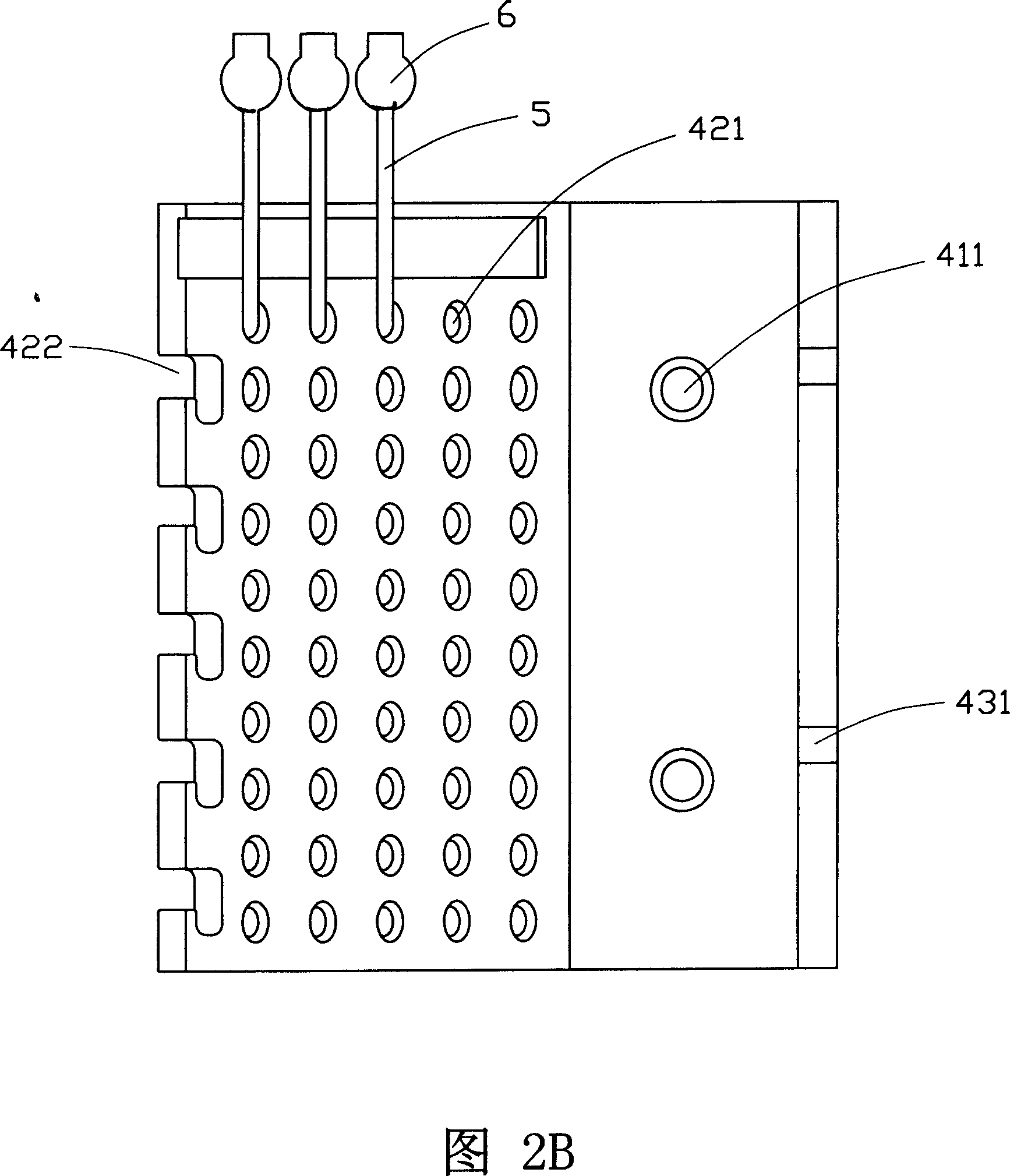
[0015] Below in conjunction with accompanying drawing, the present invention will be further elaborated. Referring to FIG. 1 , a junction box 10 for terminalless communication cables at least includes a box body 1 , a crossbeam 2 inside the box, and a longitudinal beam 3 inside the box. Several rows of wiring function boards 4 are arranged on the longitudinal beam 3 inside the junction box. Several rows of perforations 421 are arranged on the described wiring function board, and each perforation can be worn to put cable 5, and a pair of cable core wires can be worn at least in each hole, and each core wire is connected with terminal 6 again.

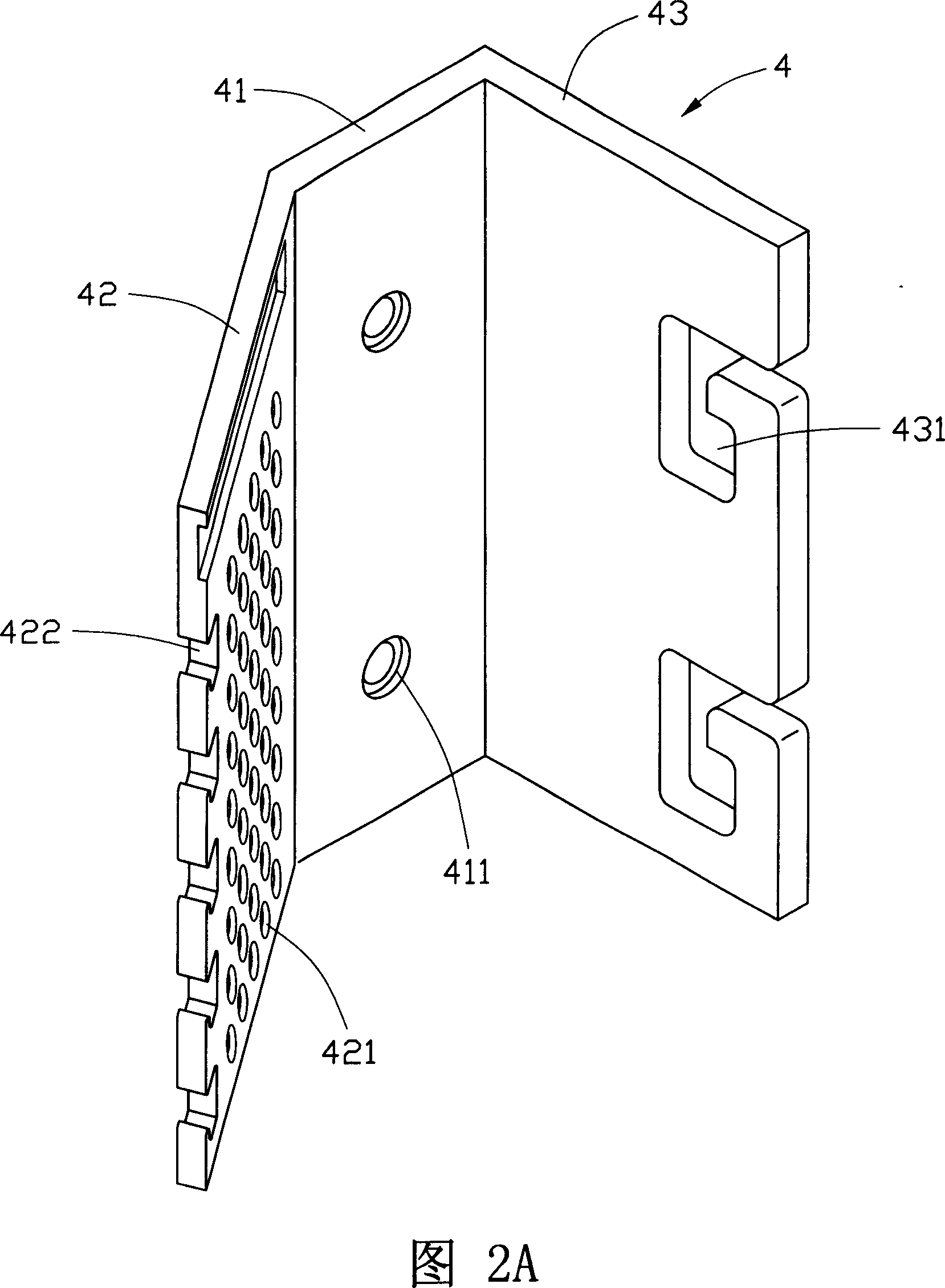
[0016] Referring again to FIG. 2 , the wiring function board 4 is roughly in the shape of a “V” and includes a fixing portion 41 , a threading portion 42 and a stringing portion 43 . The fixing part 41 is provided with screw holes 411 for fixing on the longitudinal beam 3 in the transfer box; the threading part 42 is provided with severa...


PUM


Abstract

The invention relates to a communication cable junction box and a relative junction method, belonging to communication technical field, in particular to a non-terminal junction box and a relative junction method. The non-terminal communication cable junction box at least comprises a box, a beam, and a longitudinal beam, which is characterized in that the longitudinal beam is provided with a plurality of wiring function boards provided with a plurality of through hole rows, wherein each through hole can be through with cables, while each hole is at least through with a couple of cable cores. The cable cores pass through the through hole to be connected by a connector. And since the invention uses non-terminal junction technique, uses high-quality connector, and high-quality anti-oxidization material, the non-terminal junction technique has small volume, simple junction, wide junction range, high operating performance, and non-interference or the like, the invention can overcome the defects of prior art and reach aforementioned technique effects.

Description

technical field [0001] The invention relates to a communication cable transfer box and a connection method thereof, which belong to the technical field of communication, and in particular relate to a terminalless transfer box and a connection method. Background technique [0002] The cable transfer box for communication lines is used for the connection of urban communication cables and trunk cables and distribution cables of factory and mine telecommunication networks. Existing products are usually designed and manufactured according to the communication industry standard of the People's Republic of China---YD / T611-93 "Communication Cable Junction Box". The most common feature is the use of modules as transfer terminals. For example, the "communication cable transfer box module" disclosed in Chinese patent CN2163495Y, and the "straight-type quick connection module" of CN2178030 all involve using terminal modules as connection methods. However, there are certain deficiencie...

Claims


Application Information

Patent Timeline
Patent Type & Authority Applications(China)
IPC IPC(8): H04Q1/06
Inventor 蔡志祥
Owner 昆山市大唐通讯设备有限公司
Why Eureka
Try Eureka