System and method for detecting eas/rfid tags using step listen

A technology of labels and anti-theft systems, applied in the field of identification labels, can solve problems such as complex RTF

Inactive Publication Date: 2008-01-02
CHECKPOINT SYST INC
View PDF1 Cites 14 Cited by
  • Summary
  • Abstract
  • Description
  • Claims
  • Application Information

AI Technical Summary

Problems solved by technology

Therefore, RTF is more complex in both modes, and the present invention is concerned with RTF operations

Method used


Image

  • System and method for detecting eas/rfid tags using step listen
  • System and method for detecting eas/rfid tags using step listen
  • System and method for detecting eas/rfid tags using step listen

Examples


Embodiment Construction

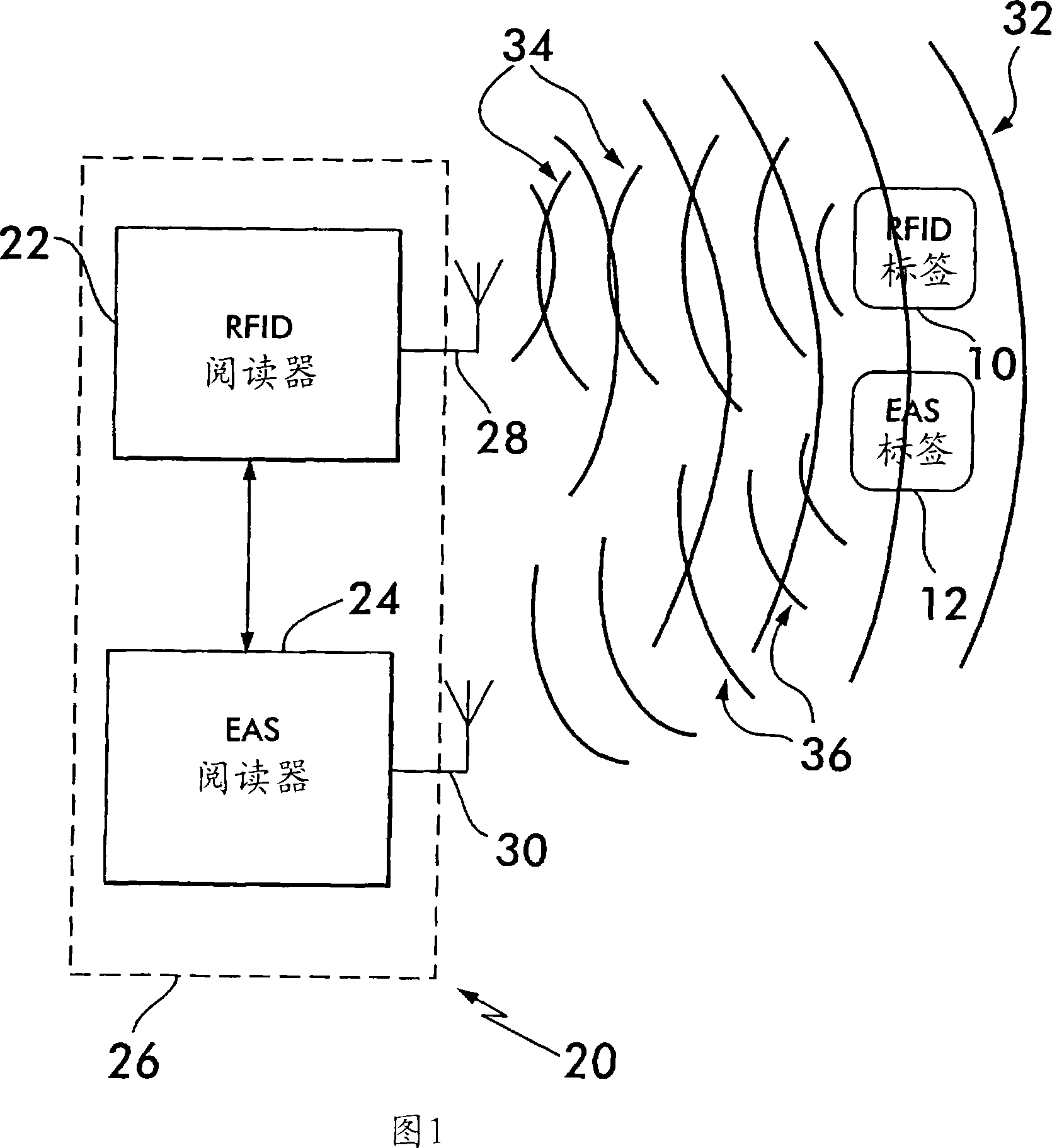
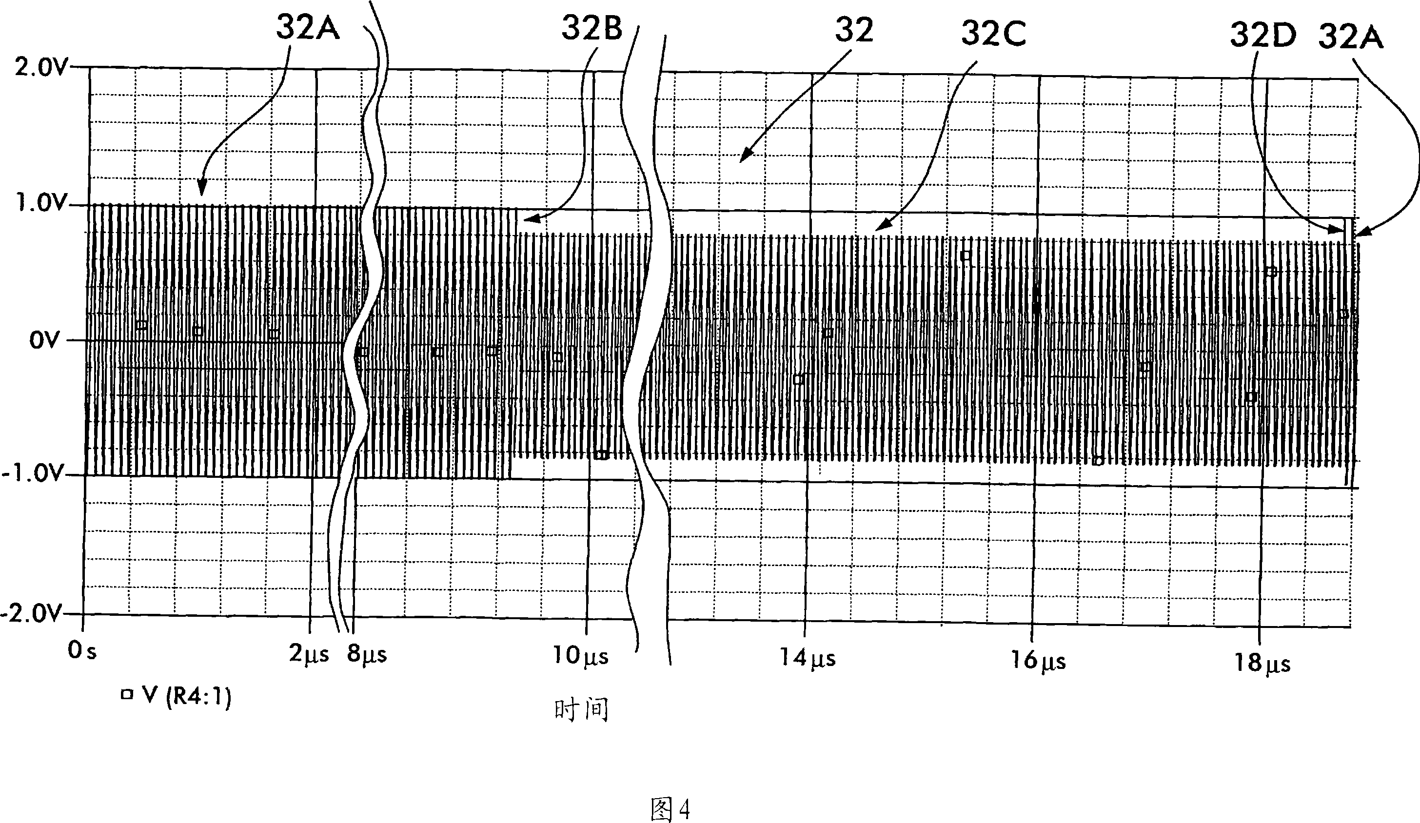
[0034]As shown in FIG. 1 , the present invention 20 generally includes an RFID reader 22 and an EAS step-listening receiver 24 located in a single housing 26 and each having a respective antenna 28 and antenna 30 . In operation, the RFID reader 22 transmits an excitation signal 32 (FIG. 4) comprising an RFID carrier frequency (eg, 13.56 MHz) and modulated by RTF commands. If an RFID tag 10 is present and tuned to the RFID frequency, the RFID tag 10 transmits a response signal 34 detectable by the RFID reader 22 (FIG. 5). If an EAS tag 12 is also present nearby and tuned to an EAS frequency (e.g., 8.2 MHz), then the EAS tag 12 transmits (FIG. 6) a natural response "ring" signal 36 that can be detected by the EAS step listening receiver 24 ( caused by the excitation signal 32). It should be appreciated that the excitation signal 32 and the "ring" signal 36 occur approximately simultaneously, while the RFID response signal 34 occurs later.

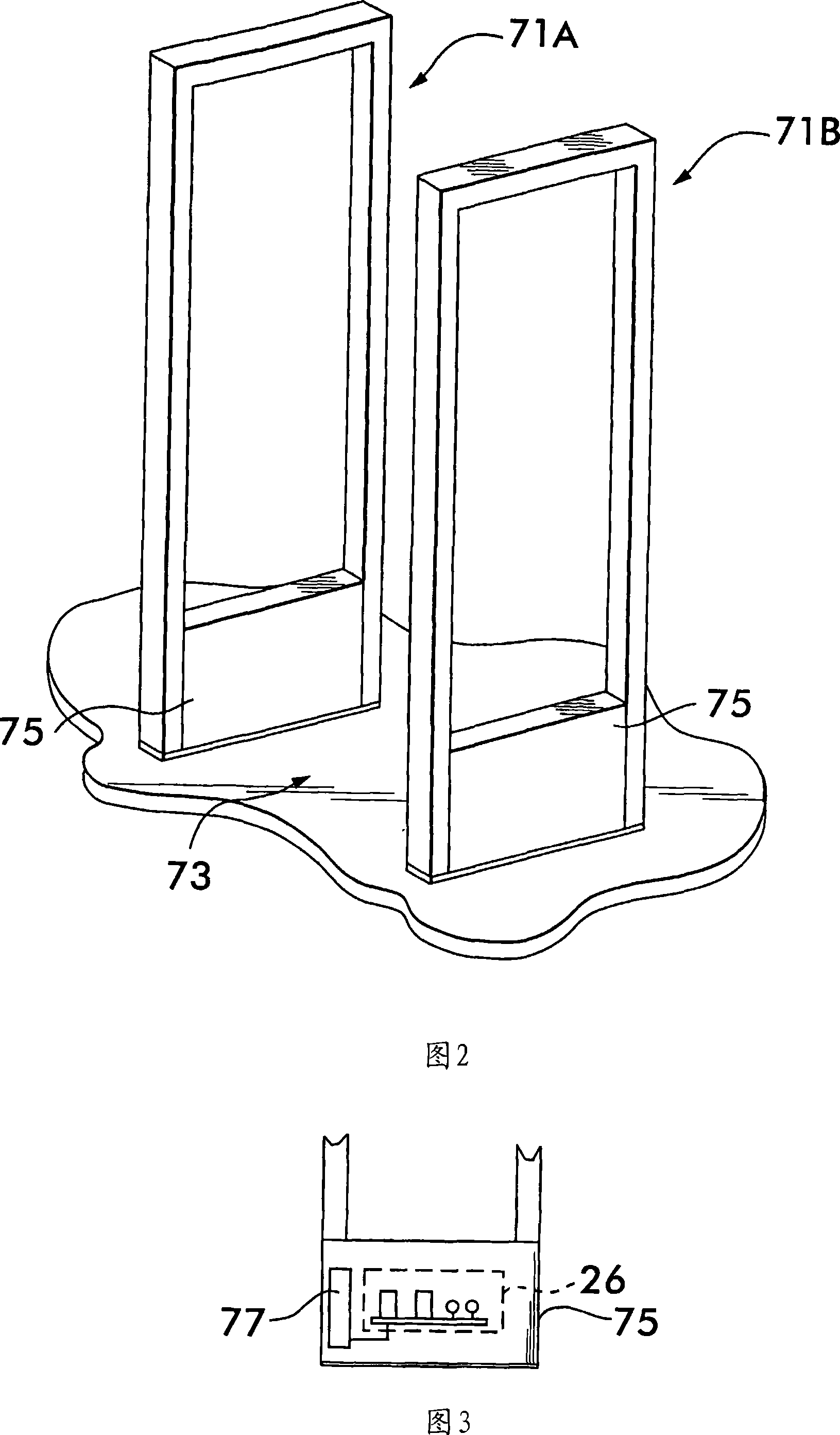
[0035] FIG. 2 depicts an exemplary p...


PUM


Abstract

A system and method for the real-time concurrent detection of 13.56 MHz RFID and 8.2 MHz EAS identification tags using a single stimulus signal.

Description

technical field [0001] The invention mainly relates to identification tags, and in particular to a system and method for simultaneously detecting 8.2MHz EAS tags and 13.56MHz ISO15693 RFID tags. Background technique [0002] The use of EAS (Electronic Article Surveillance System) tags and RFID (Radio Frequency Identification) tags for various reading, tracking and / or detection applications is rapidly expanding. A smooth connection between the functionality of existing EAS and RFID is a consistent theme identified by users interested in RFID in order to allow them to profit from RFID while maintaining their high performance in EAS technology and unproven RFID Cost-effectively protects the investment in the practicality of low-cost sales objects. However, conventional methods of processing the respective EAS or RFID signals returned from tags exhibit certain disadvantages or limitations when identifying the frequencies at which the tags are capable of receiving EAS and RFID. ...

Claims


Application Information

Patent Timeline
Patent Type & Authority Applications(China)
IPC IPC(8): G08B13/24
Inventor 罗纳德·萨勒斯凯约翰·帕拉齐诺尼斯·沙阿
Owner CHECKPOINT SYST INC
Why Eureka
Try Eureka