Wear resistant, heat resistant conveyor chain

A conveyor chain, heat resistance technology, applied in the field of conveyor chains, can solve problems such as uneven wear, increased chain wear and elongation, and damage to chain life, so as to maintain the life of the chain and inhibit chain wear and elongation.

Inactive Publication Date: 2008-01-09
TSUBAKIMOTO CHAIN CO
View PDF1 Cites 4 Cited by
  • Summary
  • Abstract
  • Description
  • Claims
  • Application Information

AI Technical Summary

Problems solved by technology

[0004] However, in the conveyor chain as described above, metal abrasion powder generated due to the sliding contact between the roller end surface of the roller and the inner surface of the inner link plate invades between the inner peripheral surface of the roller and the outer peripheral surface of the sleeve. , this kind of metal wear powder becomes an abrasive material and causes abnormal uneven wear between the roller and the sleeve. The life of the chain is greatly increased, and the sliding noise of the chain is seriously increased.

Method used


Image

  • Wear resistant, heat resistant conveyor chain
  • Wear resistant, heat resistant conveyor chain
  • Wear resistant, heat resistant conveyor chain

Examples


Embodiment Construction

[0024] Hereinafter, the wear-resistant and heat-resistant conveyor chain 100 which is one Example of this invention is demonstrated based on drawing.

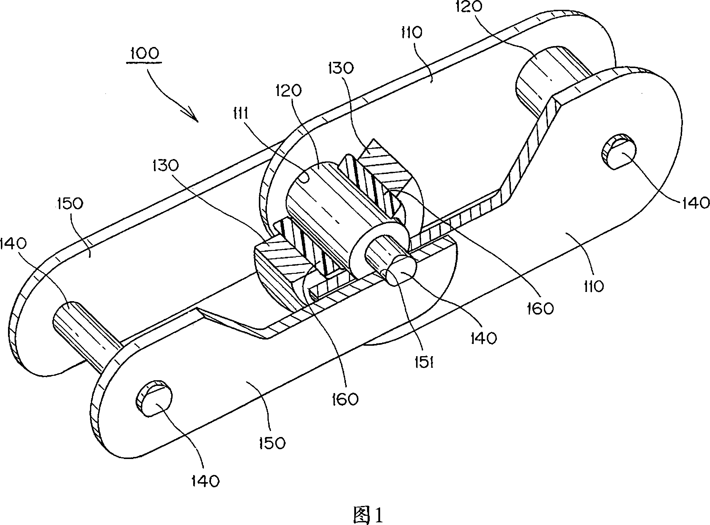
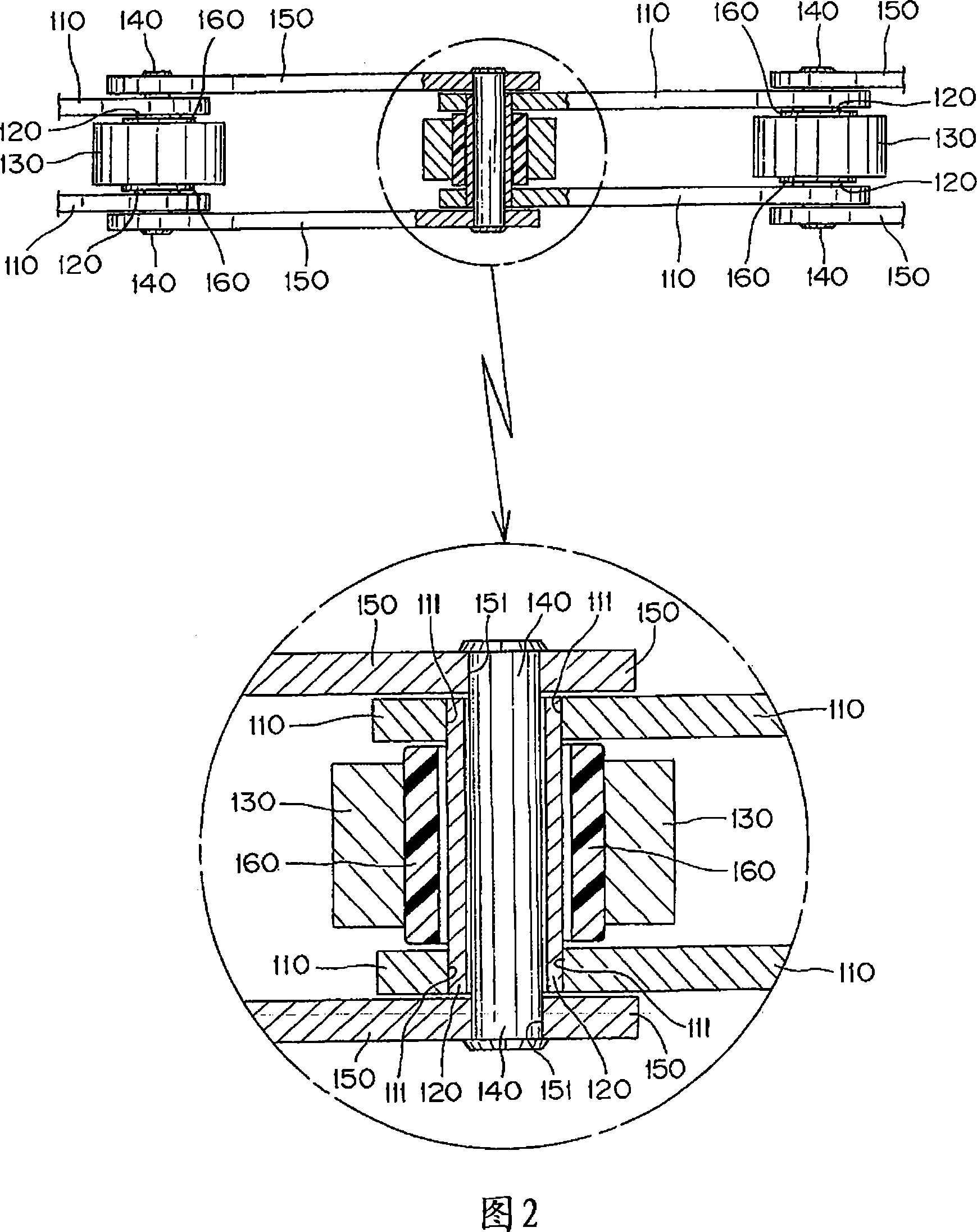
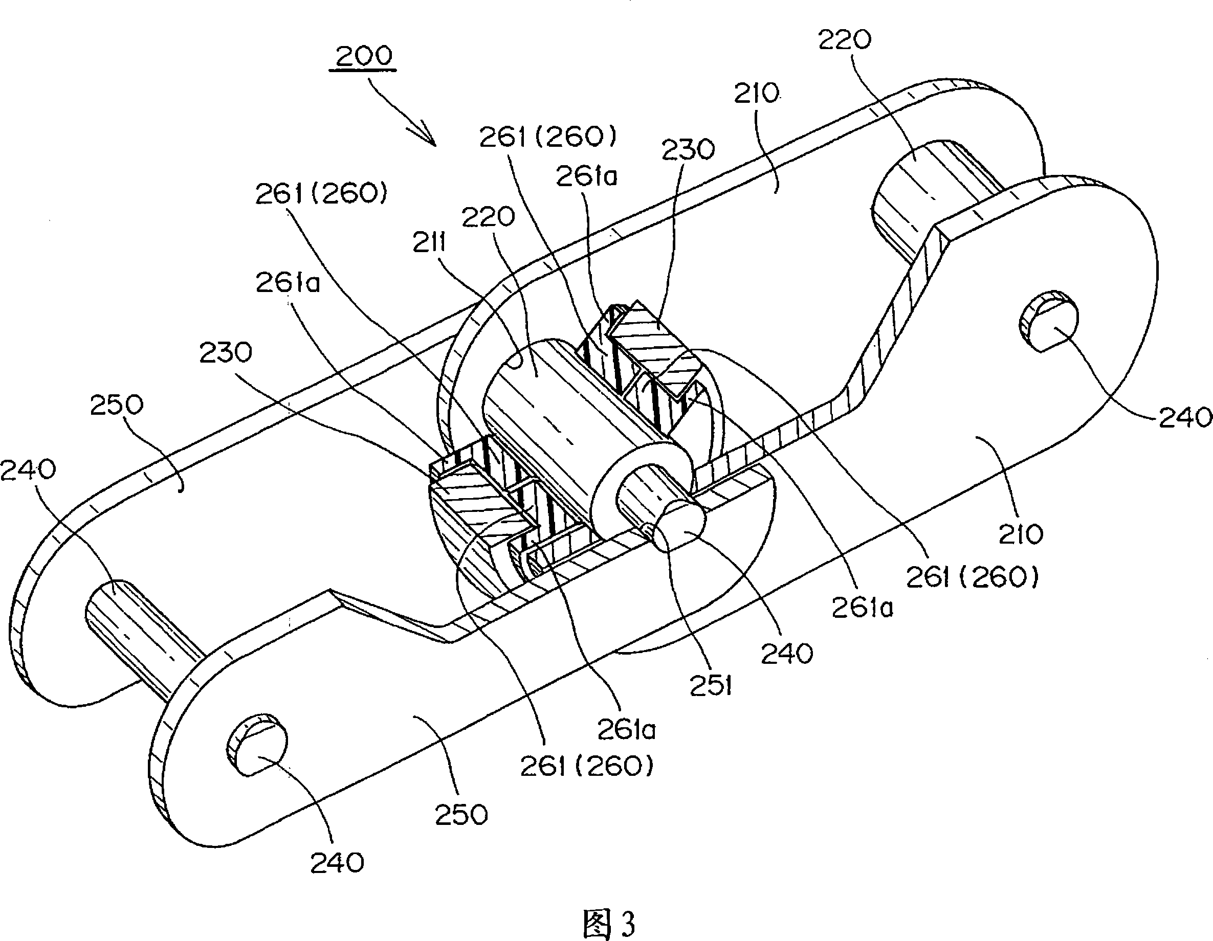
[0025] Here, FIG. 1 is a schematic diagram of a wear-resistant and heat-resistant conveyor chain as a first embodiment of the present invention, and FIG. 2 is a partial cross-sectional view of the wear-resistant and heat-resistant conveyor chain shown in FIG. An enlarged view of its important parts, FIG. 3 is a schematic diagram of a wear-resistant and heat-resistant conveyor chain as a second embodiment of the present invention, and FIG. 4 is a wear-resistant and heat-resistant conveyor chain shown in FIG. 3 A section view of a part of a chain and a zoom-in view of its important parts.

[0026]First, as shown in FIGS. 1 and 2 , a wear-resistant and heat-resistant conveyor chain 100 according to a first embodiment of the present invention includes a pair of left and right inner plates 110 spaced apart, press-fitted and fitted i...


PUM


Abstract

A wear resistant, heat resistant conveyor chain comprising a series of links, each having a heat resistant roller rotatably fitted onto a bush between inner plates. The links are interconnected in the longitudinal direction of the chain by outer plates, and connecting pins rotatably inserted into the bush. A wear resistant, heat resistant sleeve-shaped spacer protrudes beyond the end surfaces of the heat resistant rollers toward the right and left inner plates to eliminate any sliding contact between the end surface of the heat resistant roller and the inner side surface of the inner plate.

Description

technical field [0001] The present invention relates to a wear-resistant and heat-resistant conveyor chain used in conveying equipment, and more specifically, to a wear-resistant and heat-resistant conveyor chain used in a heat-resistant working environment such as a bread oven. chain. Background technique [0002] Conventionally, as a conveyor chain used in severe environments such as heat resistance, there is known a conveyor chain in which a plurality of link plates are interlocked with link pins and rollers are attached to each link plate with a sleeve. In the conveyor chain on the above-mentioned link pin, the sleeve is made of stainless steel, and the roller is made of PEEK resin (polyether ether ketone resin) at least in the inner diameter portion (for example, refer to Patent Document 1.). [0003] Patent Document 1: Japanese Patent Application Laid-Open No. 6-227632 (see column 1, FIG. 3 ) [0004] However, in the conveyor chain as described above, metal abrasion ...

Claims


Application Information

Patent Timeline
Patent Type & Authority Applications(China)
IPC IPC(8): B65G17/24B65G17/38
CPCB65G17/38B65G2207/48B65G2207/12F16G13/06
Inventor 中川贵司石田裕树藤原诚中村隆太郎
Owner TSUBAKIMOTO CHAIN CO
Why Eureka
Try Eureka