Engine exhaust valve structure

A technology for exhaust valves and engines, which is applied in the direction of engine components, machines/engines, mechanical equipment, etc., and can solve the problem of exhaust valve rod and valve guide wear, exhaust valve rod rotation is not obvious, and exhaust valve rod cone burnt Damage and other problems, to achieve the effect of preventing fracture, obvious rotation effect and improving sealing performance

Inactive Publication Date: 2012-08-22
力帆科技(集团)股份有限公司
View PDF0 Cites 3 Cited by
  • Summary
  • Abstract
  • Description
  • Claims
  • Application Information

AI Technical Summary

Problems solved by technology

[0005] 1. The offset between the axis line of the valve clearance adjustment screw and the axis line of the exhaust valve stem is not easy to control, the rotation of the exhaust valve stem around its axis is not obvious during work, and the conical surface of the exhaust valve stem will still be affected by the Burning due to local overheating
[0006] 2. There is an offset between the axis line of the valve clearance adjustment screw and the axis line of the exhaust valve stem, which will cause the exhaust valve stem to receive side pressure. The larger the offset, the greater the side pressure on the exhaust valve stem. Larger, which will cause greater wear between the exhaust valve stem and the valve guide, and in severe cases will cause the exhaust valve stem to break, thereby shortening its service life

Method used


Image

  • Engine exhaust valve structure
  • Engine exhaust valve structure
  • Engine exhaust valve structure

Examples


Embodiment Construction

[0014] Below in conjunction with accompanying drawing and embodiment the present invention will be further described:

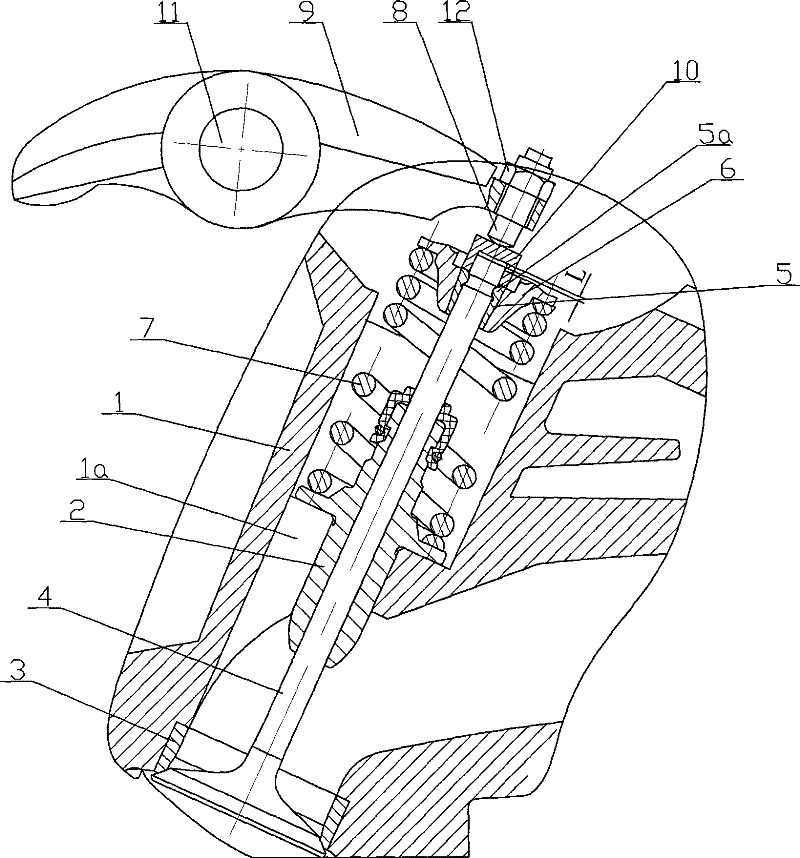
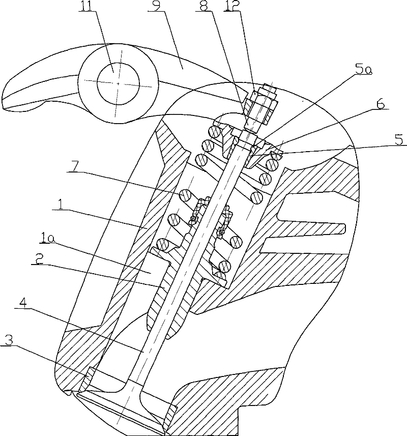
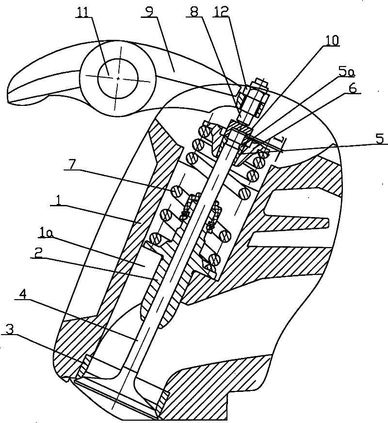
[0015] like figure 1 As shown, a valve guide 2 and a valve seat 3 are installed at the middle of the accommodation hole 1 a on the cylinder head 1 , and the valve guide 2 and the valve seat 3 are tightly fitted with the cylinder head 1 . The exhaust valve rod 4 passes through the valve seat 3 and the valve guide 2 from bottom to top, and the valve lock clip 5 is installed on the top of the exhaust valve rod 4, and the arc-shaped boss 5a on the inner wall of the valve lock clip 5 snaps into the row. The corresponding arc-shaped ring groove on the valve stem 4, and the arc-shaped boss 5a is slightly smaller than the arc-shaped ring groove matched therewith. The upper spring seat 6 is set on the outside of the valve lock clip 5, and the valve spring 7 upper end on the exhaust valve rod 4 is limited by the spring upper seat 6, and the lower end is limited by th...


PUM


Abstract

This invention is engine exhausting valve structure. The exhausting valve stem passes through exhausting valve base and valve guide pipe. The top of the exhausting valve stem is assembled with valve lock clamp. Outside of the valve lock clamp is spring base. The valve spring is arranged on the exhausting valve stem. There is valve gap setting screw above the top of the exhausting valve stem. The axes of the said screw and exhausting valve stem are at the same line. There is end cap between valve gap setting screw and exhausting valve stem. The said end cap covers on the exhausting valve stem through its dead hole which is at the bottom. There is certain space between the end face of the said dead hole and the top face of exhausting valve stem. This invention can prevent the local overheatof exhausting valve stem and prevent rupture of exhausting valve stem.

Description

technical field [0001] The invention belongs to the technical field of engines, and in particular relates to an engine exhaust valve structure. Background technique [0002] The exhaust valve rod is installed in the cylinder head of the engine, which plays the role of sealing and controlling exhaust, and is an important part of the engine. The installation method of the existing exhaust valve stem is as follows: figure 2 As shown, the valve guide 2 is installed in the middle of the accommodation hole 1a on the cylinder head 1, and the valve seat 3 is installed at the bottom. The exhaust valve stem 4 passes through the valve seat 3 and the valve guide 2 from bottom to top, A valve lock clip 5 is installed on the top of the rod 4, and the arc-shaped boss 5a on the inner wall of the valve lock clip is snapped into the corresponding arc-shaped ring groove on the exhaust valve rod 4. The lower end of the valve spring 7 on the exhaust valve rod 4 is limited by the annular boss i...

Claims


Application Information

Patent Timeline
Patent Type & Authority Patents(China)
IPC IPC(8): F01L1/18
Inventor 王胜华
Owner 力帆科技(集团)股份有限公司
Why Eureka
Try Eureka