
Double-shaft hinge device

A technology of biaxial hinges and hinges, which is applied in the direction of hinges with pins, pivot connections, transmission systems, etc., can solve the problems of high manufacturing costs of hinge devices, and achieve the effect of cheap manufacturing costs and reduced manufacturing costs

Inactive Publication Date: 2008-01-09
SUGATSUNE IND CO LTD
View PDF1 Cites 14 Cited by
  • Summary
  • Abstract
  • Description
  • Claims
  • Application Information

AI Technical Summary

Problems solved by technology

Therefore, there is a problem that the manufacturing cost of the hinge device is high.

Method used


Image

  • Double-shaft hinge device
  • Double-shaft hinge device
  • Double-shaft hinge device

Examples


Embodiment Construction

[0043] Preferred embodiments for carrying out the present invention will be described below with reference to the drawings.

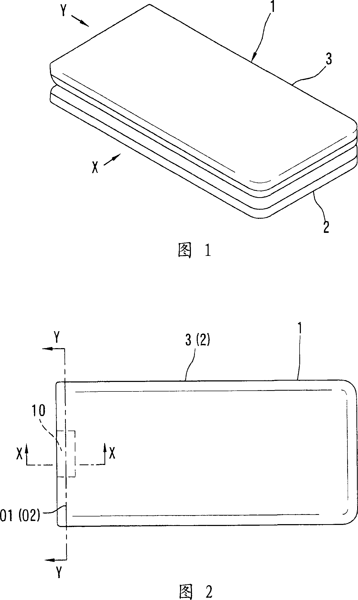
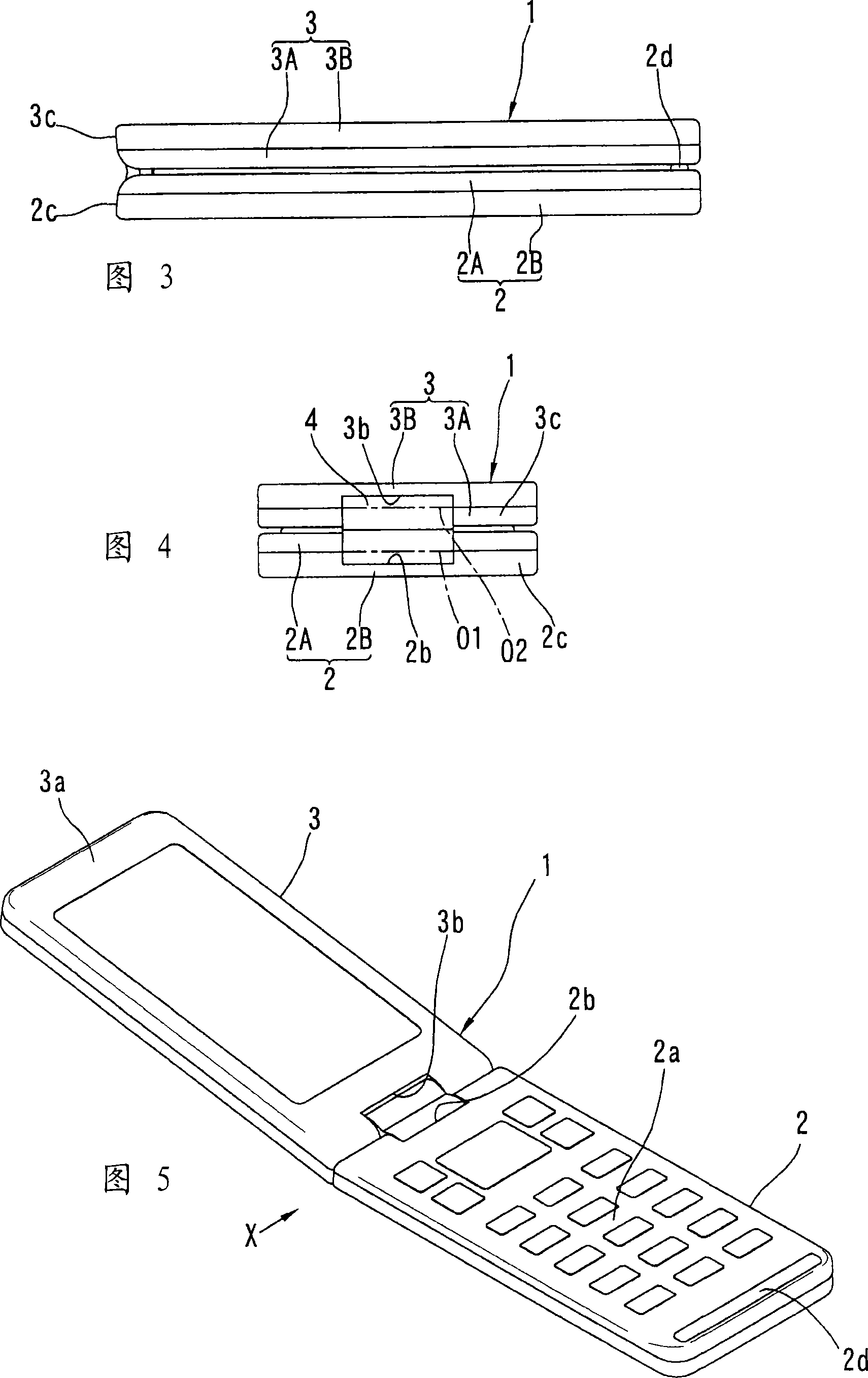
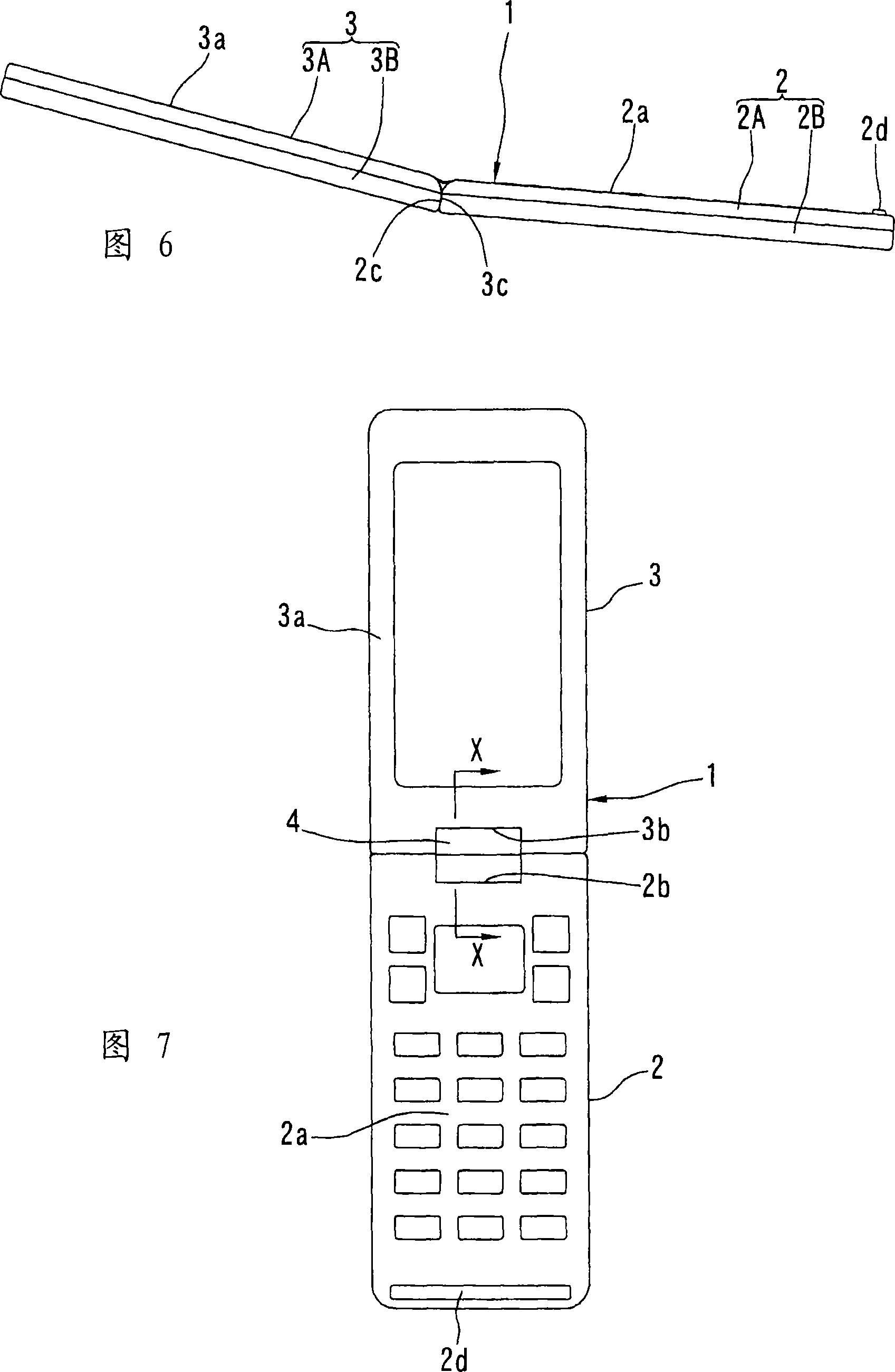
[0044] 1 to 11 show a mobile phone 1 using a hinge device 10 of the present invention. The mobile phone 1 includes a talking side housing 2 and a receiving side housing 3 . One end of the calling-side housing 2 and one end of the receiving-side housing 3 are connected by a hinge device 10 so as to be rotatable.

[0045] The communication-side housing 2 is composed of two half bodies 2A and 2B, and is formed in a relatively thin rectangular parallelepiped shape. As shown in FIGS. 8 to 11 , a mounting recess 2 b is formed at one end in the longitudinal direction of the front surface 2 a of the communication side housing 2 . The receiving side housing 3 is composed of two halves 3A, 3B, and is formed in a relatively thin rectangular parallelepiped shape. The top view shape of the receiving side frame 3 is substantially the same as the top view shape of ...


PUM


Abstract

The present invention provides a biaxial hinge device which is manufactured cheaply. Setting a first and a second rotational component (22, 23) on the hinge main body which rotate surrounding a first and a second rotational axes (01, 02) paralleling to each other separately. Connecting one end of a connecting bar (34) to the first rotational component (22), the connecting bar (34) rotates surrounding a third rotational axes (03) which is parallel to the first and the second rotational axes (01, 02); the other end of the connecting bar (34) connects to the second rotational component (23) and rotates surrounding a fourth rotational axes (04) which is parallel to the first and the second rotational axes (01, 02). The third and the fourth rotational axes (03, 04) are configured on the opposite side of the line which passes through the first and the second rotational axes (01, 02).

Description

technical field [0001] The invention relates to a biaxial hinge device suitable for portable devices such as game machines and mobile phones. Background technique [0002] Generally speaking, a biaxial hinge device includes: a hinge main body; first and second rotating parts, which are arranged to be able to rotate around the first and second rotating axes parallel to the hinge main body; the first and second rotating parts Two gears are respectively arranged on the first and second rotating parts and cannot rotate. The first and second gears mesh with each other. In this way, the first and second rotating parts rotate in a mutually interlocking state. [0003] But when using the first and second gears to connect the first and second rotating parts with each other, only the backlash between the first and second gear tooth surfaces will make the first and second rotating parts There is a problem of looseness in the circumferential direction. This is when the two-axis hing...

Claims


Application Information

Patent Timeline
IPC IPC(8): F16C11/04H04M1/02
CPCG06F1/1616G06F1/1681H04M1/022E05D3/12E05D11/06E05D11/084E05Y2999/00H04B1/38
Inventor 冨泽健二幡野裕一
Owner SUGATSUNE IND CO LTD
Features
  • Generate Ideas
  • Intellectual Property
  • Life Sciences
  • Materials
  • Tech Scout
  • Unparalleled Data Quality
  • Higher Quality Content
  • 60% Fewer Hallucinations
Learn More