Thin type CD-ROM drive tray structure

A technology for trays and optical drives, which is applied in the direction of record carrier structural parts, instruments, data recording, etc., can solve the problems of time-consuming manufacturing and assembly, high cost, and many components.

Inactive Publication Date: 2008-01-09
QUANTA STORAGE INC
View PDF0 Cites 4 Cited by
  • Summary
  • Abstract
  • Description
  • Claims
  • Application Information

AI Technical Summary

Problems solved by technology

Although the weight of the optical drive can be reduced, there are still many components, time-consuming manufacturing and assembly, and high cost

Method used


Image

  • Thin type CD-ROM drive tray structure
  • Thin type CD-ROM drive tray structure
  • Thin type CD-ROM drive tray structure

Examples


Embodiment Construction

[0015] The technical means adopted by the present invention to achieve the above-mentioned purpose and its effects are described as follows with reference to preferred embodiments and accompanying drawings.

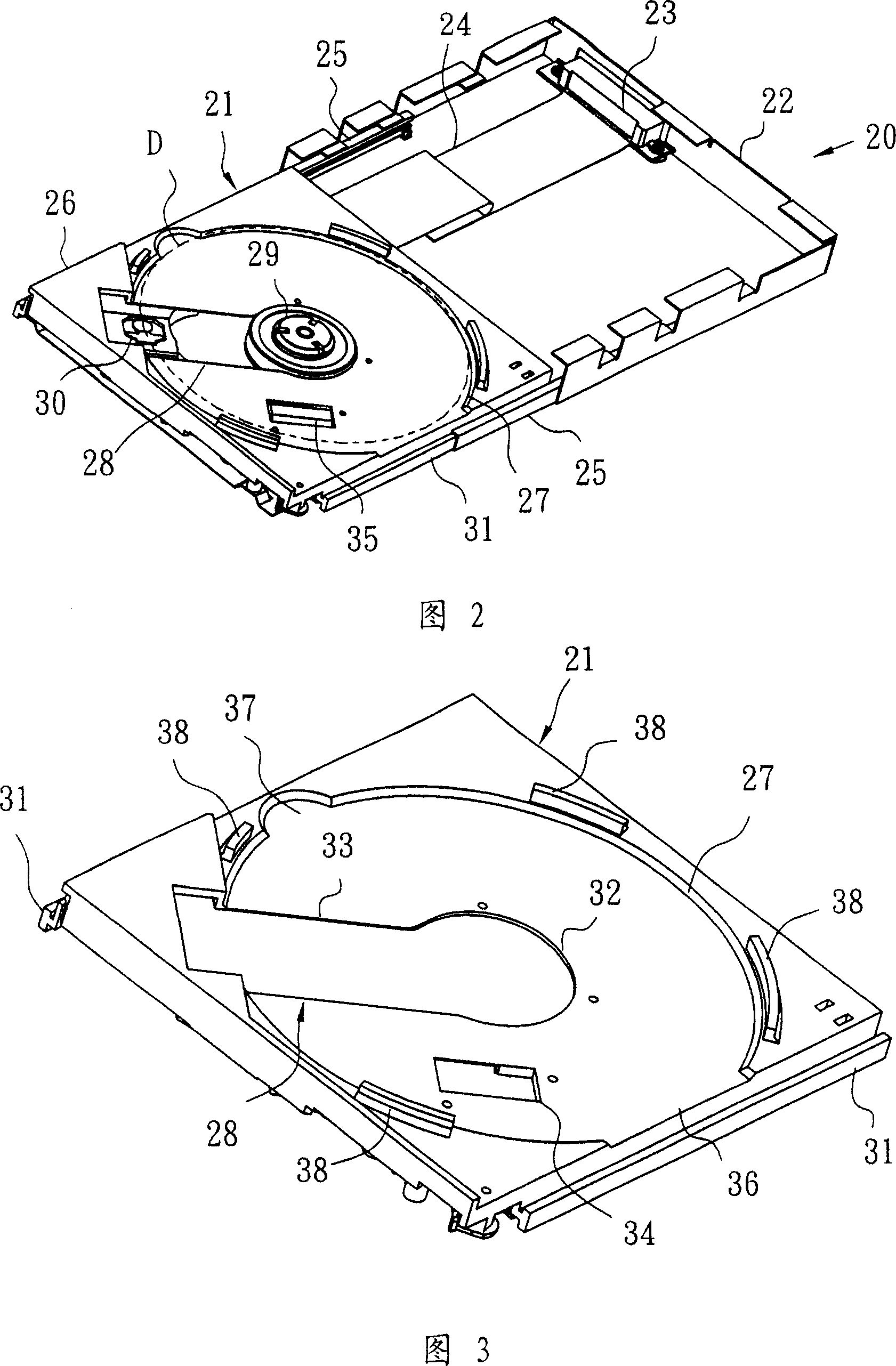
[0016] Referring to FIG. 2 , FIG. 2 is an internal structure of a thin optical drive 20 using the tray 21 of the present invention. The thin optical drive 20 includes a tray 21 , a casing 22 , a connector 23 , a cable 24 , a guide rail 25 and the like. The hollow interior mainly composed of the housing 22 accommodates the tray 21. The rear end of the tray 21 is connected to the cable 24, and the other end of the cable 24 is connected to the connector 23 provided at the rear end of the housing 22. The tray 21 is supported by guide rails 25 on both sides. , can slide in and out of the casing 22 of the slim optical drive 20 .

[0017] Wherein, the tray 21 is basically a body 26 of a rectangular flat body, and a nearly circular bearing groove 27 is recessed in the center, an...


PUM


Abstract

Its main body (MB) is a flat rectangle with a concave bear groove (BG) in the center. The shape of BG is near round. One side of BG forms an open edge while the opposite side spreads out to form a picking groove. There are several allocation blocks separately set on the outside of the BG edge. There is a configuration hole (CH) on BG. One end is a fixing hole while the other end is a rectangle hole. Near CH, an embedding hole (EH) is on BG, too. There are strengthening tendon (ST) and several fixing screws (FS) on the back of MB. Around ST, there are CH and EH near FS. There are two slide rails on each side of MB. All mentioned parts combine into an integrated body.

Description

technical field [0001] The invention relates to a thin optical drive, in particular to the structure of the tray in the thin optical drive. The tray of the thin optical drive is formed by using a simple integrally formed structure. Background technique [0002] Optical drives are distinguished by thickness, mainly divided into half-height type and thin type. For half-height optical drives, the core is installed in the casing, and only the tray enters the drive. Since the core and the tray are set separately, the tray can be formed independently without restriction, but the thickness is relatively thick, which is not conducive to installation and carrying. The thin optical drive core is directly arranged on the tray, and enters the optical drive advance and retreat with the tray. The thickness of the body is relatively thin, which is conducive to installation and carrying. However, due to the core including high-speed moving components, the structure and strength of the tray ...

Claims


Application Information

Patent Timeline
IPC IPC(8): G11B17/04G11B17/056G11B33/00
Inventor 吴仁琛蔡耀庆郭耀庭
Owner QUANTA STORAGE INC
Why Eureka
Try Eureka