Image shooting method of display device

A technology of a display device and a shooting method, applied in image communication, parts of color TV, parts of TV system, etc., can solve the problems of dark field or total black, screen flicker, unevenness, etc., and achieve good shooting effect Effect

Inactive Publication Date: 2008-01-09
GUANGDONG VTRON TECH CO LTD
View PDF0 Cites 17 Cited by
  • Summary
  • Abstract
  • Description
  • Claims
  • Application Information

AI Technical Summary

Problems solved by technology

When randomly shooting the screen of a display device, such as taking a photo of a TV image, when the shutter is opened, the scanning light spot on the TV fluorescent screen cannot fall on the starting point of the image scanning, and a dark field or total black ph

Method used


Image

  • Image shooting method of display device
  • Image shooting method of display device

Examples


Embodiment 1

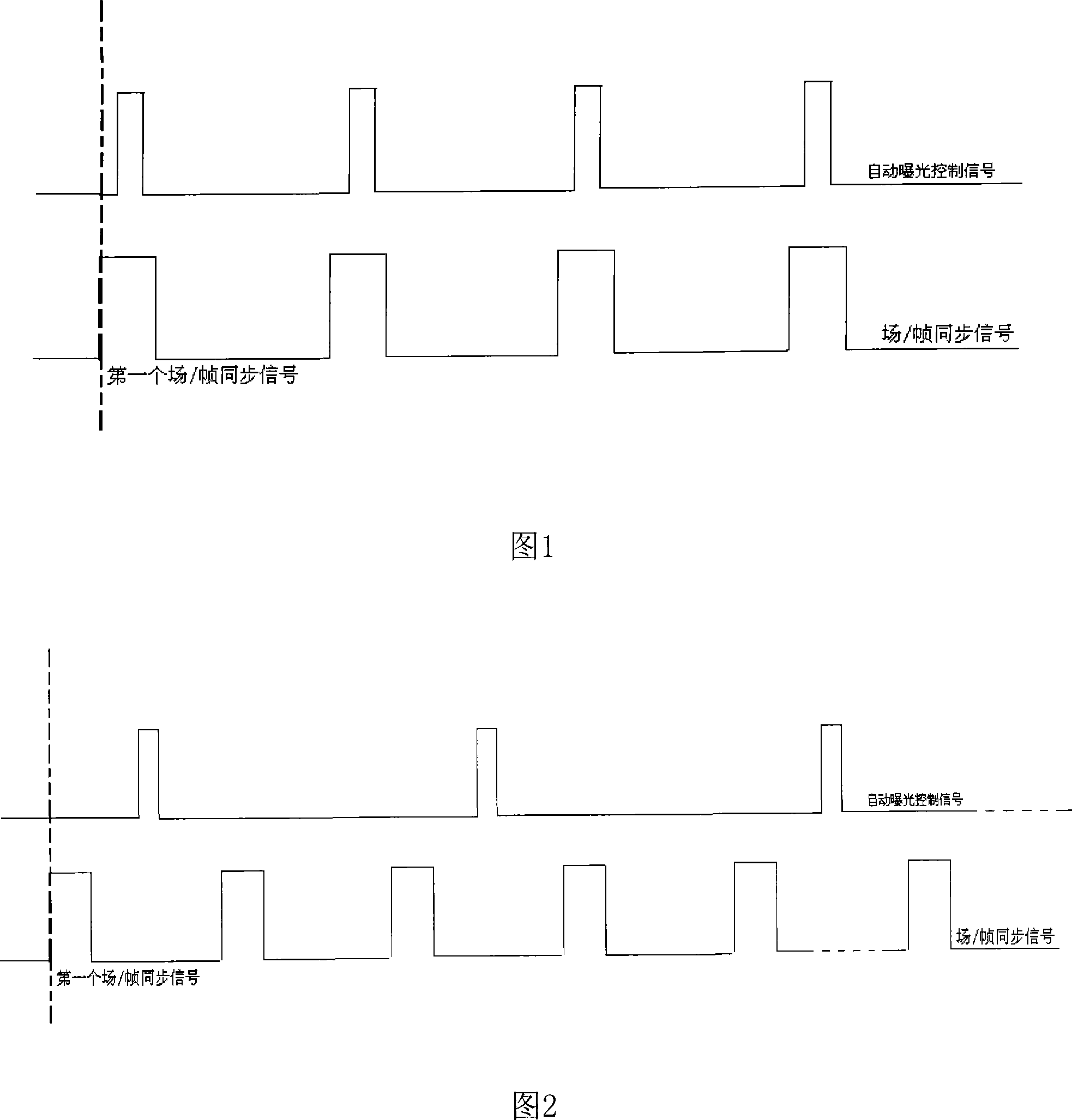
[0018] When using the image shooting method of the display device, when shooting a TV (CRT display device) with a known refresh rate, the exposure time of the shooting device is set as the refresh cycle of the TV, so as to synchronously shoot the TV.

[0019] TV images are formed by spot scanning, such as 25 frames per second in PAL system and 30 frames per second in NTSC system, etc., when using synchronous shooting, set the exposure time as the refresh cycle of PAL or NTSC, as shown in Figure 1, the shutter Start to open, the device captures the first field synchronous signal after that, and enters the state of synchronous shooting of a frame of TV image. After shooting a frame of TV image, close the shutter, and then open it when the field synchronous signal of the next frame of image arrives. Considering that the shutter The opening transient process (the time from the shutter opening to the full opening) is the time lag of the shutter, and the shutter is opened in advance ...

Embodiment 2

[0021] Using the method for shooting images of the display device, when shooting a multi-projection display device with a known refresh rate, such as a DLP (Digital Light Processor), it is synchronous shooting. The display principle of DLP is: the projector bulb emits light, and the white light source is focused on the color separation wheel through the condenser lens. The color separation wheel is composed of red, green, and blue filter systems. It rotates at a frequency of 60Hz. In this structure, DLP works in sequential color mode. Therefore, the shooting device only needs to capture the first red light signal projected in each frame as the starting moment of exposure, and the exposure time is the projection period or N times of the projection period, where N is an integer greater than 1.

Embodiment 3

[0023] As shown in Figure 1, when adopting the photographing method of this display device image, when shooting the dynamic images based on field and frame scanning LCD and PDP display devices, the exposure time of the photographing device is set to be the refresh cycle of the TV, which is synchronous shooting. As shown in Figure 1, the shutter starts to open, and the device captures the first field synchronization signal after that, and enters the state of synchronous shooting of one frame of image. After shooting one frame of image, close the shutter until the field synchronization signal of the next frame of image arrives. Opening, taking into account the shutter opening transient process (the time from the beginning of the shutter to full opening), that is, the time lag of the shutter, the shutter is opened in advance before the arrival of the field synchronization signal.


PUM


Abstract

The method comprises: according to the refreshing frequency of the display, setting the exposure time of the camera as N times of the refreshing cycle of the display, N>1; making sync shooting or non-sync shooting to the images on the display. The display is a display with a given refreshing frequency, such as a CRT display, a project display, a frame scan LCD display, a PDC display. For shooting the motion pictures on the CRT display, project display, frame scan LCD display and PDP display, the shooting is the sync shooting; for shooting still image, the shooting is non sync shooting.

Description

technical field [0001] The present invention relates to a technology for photographing images of display devices, in particular to a method for photographing images of display devices. Background technique [0002] Recently, with the advancement of computer technology, various photographing devices and display devices have been widely used. When randomly shooting the screen of a display device, such as taking a photo of a TV image, when the shutter is opened, the scanning light spot on the TV fluorescent screen cannot fall on the starting point of the image scanning, and a dark field or total black phenomenon will appear; if If the refresh rate of the display device is inconsistent with the exposure time of the shooting device, there will be screen flickering or stripes or uneven brightness, and even the photos taken are inconsistent with what you actually see. Contents of the invention [0003] The purpose of the present invention is to overcome the shortcomings and defi...

Claims


Application Information

Patent Timeline
IPC IPC(8): H04N5/232H04N5/66
Inventor 卢如西徐响林杨月
Owner GUANGDONG VTRON TECH CO LTD
Why Eureka
Try Eureka