Pressure control valve

A pressure control and pressure technology, which is applied in the field of pressure control valves of supercritical refrigeration cycles, can solve the problems of increasing the enclosed gas space, reducing equipment durability, and increasing discharge temperature, and achieves restraint of large-scale, restraint and high cost. , the effect of reducing the fluctuation of the control pressure

Inactive Publication Date: 2008-01-16
FUJIKOKI MFG CO LTD
View PDF1 Cites 8 Cited by
  • Summary
  • Abstract
  • Description
  • Claims
  • Application Information

AI Technical Summary

Problems solved by technology

[0007] However, in the pressure control valve of Patent Document 2, there is a problem that if the fluctuation of the control pressure is large relative to the displacement of the diaphragm, the control pressure deviates greatly from the high pressure (optimum pressure) at which the COP is maximum, and the COP decreases.
[0009] In addition, for the use of CO 2 For the pressure control valve of the refrigeration cycle of the refrigerant, although it is hoped that the drop of the COP relative to the control pressure is as small as possible, but to reduce the volume change of the pressure control valve relative to the valve opening, it is necessary to increase the sealed space of the enclosed gas (sensitivity) temperature part), making the pressure control valve larger and more expensive
[0010] Additionally, in CO 2 In the refrigerant refrigeration cycle, if the temperature of the refrigerant after the gas cooler rises, the optimal high pressure (the pressure at which the COP is the maximum) also rises, but if the high pressure becomes higher, the durability of the equipment decreases and the discharge temperature becomes higher

Method used


Image

  • Pressure control valve
  • Pressure control valve
  • Pressure control valve

Examples


Embodiment Construction

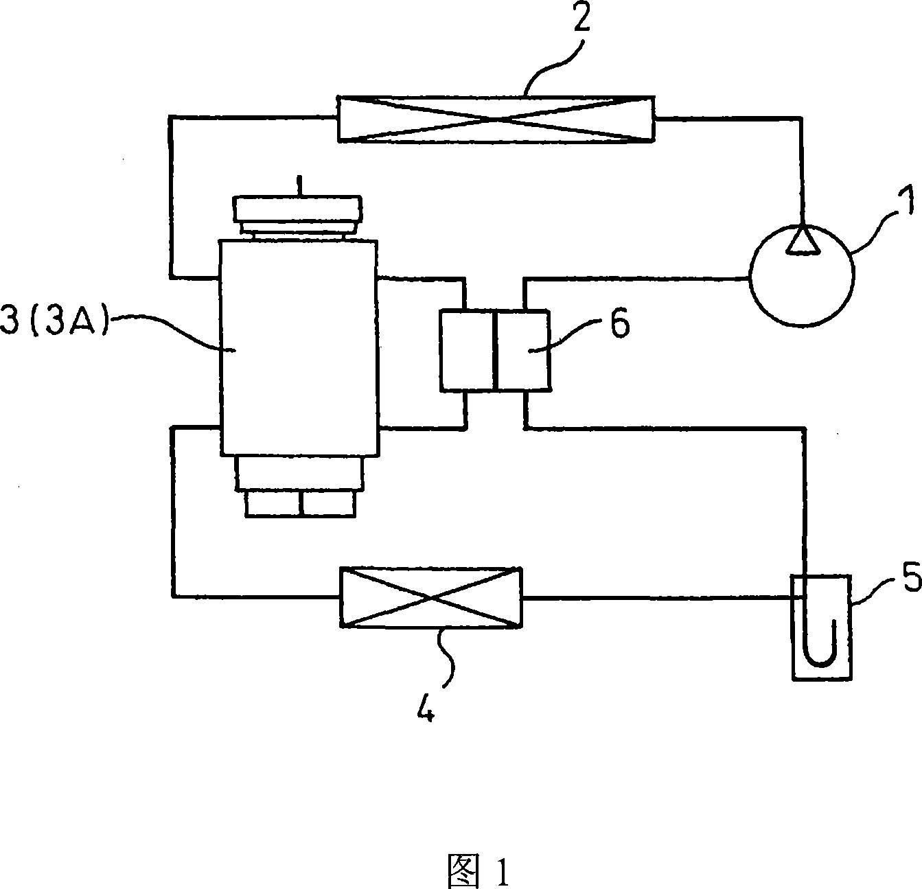
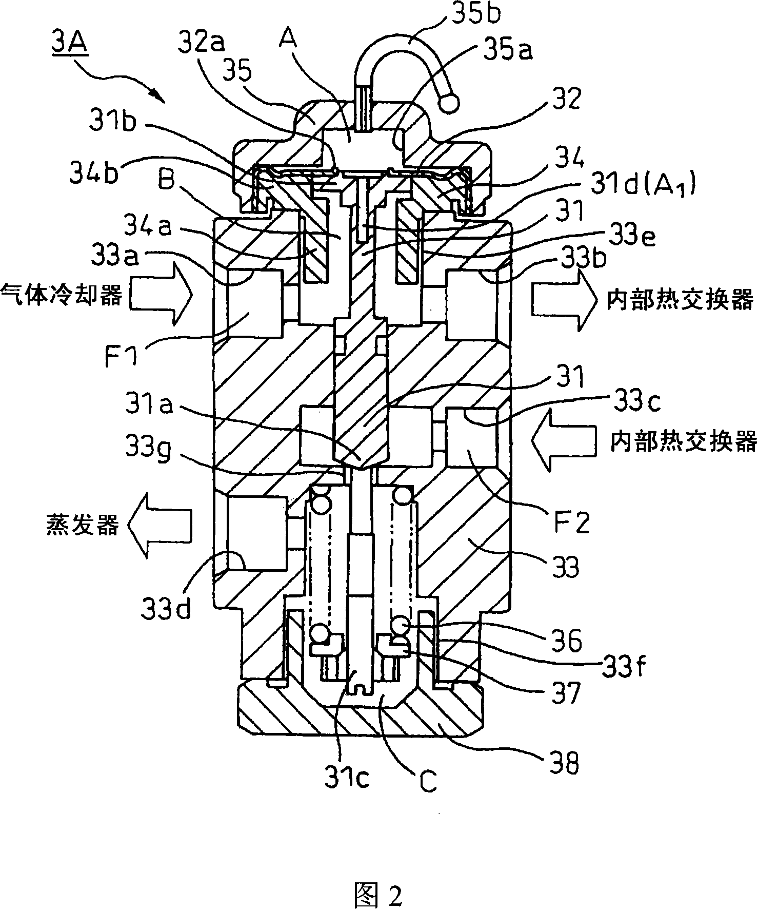
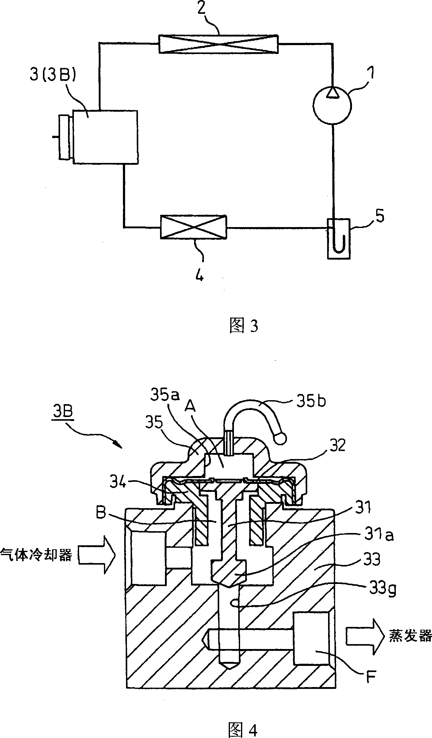
[0039] Next, a pressure control valve according to an embodiment of the present invention will be described with reference to the drawings. Figure 1 is for CO with internal heat exchanger 2 Fig. 2 is a diagram illustrating a refrigeration cycle (supercritical refrigeration cycle) in which refrigerant circulates. Fig. 2 is a pressure control valve according to a first embodiment of the present invention applied to the refrigeration cycle shown in Fig. 1 . In Figure 1, symbol 1 is inhaled CO 2 A compressor that compresses the refrigerant, and reference numeral 2 is a gas cooler (radiator) that cools the refrigerant compressed by the compressor 1 .

[0040] Reference numeral 3 is a pressure control valve (expansion valve) of this embodiment. The pressure control valve 3 has the CO 2 The temperature-sensing part (closed space) A in which the gas is enclosed controls the pressure of the refrigerant at the outlet side of the gas cooler 2 according to the temperature of the refrig...


PUM


Abstract

In a pressure controlling valve 3 for causing deformation of a resilient member 32 by a pressure difference between a CO2 gas pressure in a sealed space (heat sensitive portion) corresponding to a refrigerant temperature and a high pressure of the CO2 refrigerant in the refrigeration cycle to open and close the valve, a volume ratio Vs / (Vs-Vo) of a total volume (Vs) of the sealed space when the valve is fully closed and a total volume (Vo) of the sealed space when the valve is fully open is greater than 1.9 or 2.4. To improve this volume ratio, a cavity 31 d communicating with the sealed space is formed inside a displacement transmission member 31 coupled with the resilient member, or a recess portion 35 a is formed in a cover member 35 a, or a member communicating with the sealed space is connected.

Description

technical field [0001] The present invention relates to a pressure control valve (expansion valve) for controlling the outlet side pressure of a radiator (gas cooler) of a vapor compression refrigeration cycle, in particular to a pressure control valve (expansion valve) suitable for use in carbon dioxide (CO 2 ) and other supercritical regions using refrigerants in supercritical refrigeration cycle pressure control valves. Background technique [0002] In a conventional refrigeration cycle using HFC134a as a refrigerant, a pressure control valve as shown in FIG. 14 disclosed in Patent Document 1 is used in order to control the amount of superheated heat of the refrigerant at the outlet of the evaporator. The pressure control valve 3 has a temperature sensing part 3a whose internal pressure changes according to the temperature of the refrigerant at the outlet side of the evaporator 4; And the membrane diaphragm 3c that displaces in response to the pressure change in the temp...

Claims


Application Information

Patent Timeline
Patent Type & Authority Applications(China)
IPC IPC(8): F25B41/06F16K31/68
CPCF25B2341/0683F25B41/062F25B9/008F25B2309/061F25B2500/01Y10T137/7922F25B41/335
Inventor 太田宏已梯伸治松田亮柳泽秀
Owner FUJIKOKI MFG CO LTD
Why Eureka
Try Eureka