Ultrasound diagnosis apparatus

A diagnostic device, ultrasonic technology, applied in the directions of acoustic wave diagnosis, infrasonic wave diagnosis, ultrasonic/sonic wave/infrasonic wave diagnosis, etc., which can solve the problems of negative offset without disclosure, achieve high sensitivity, high axial resolution, and improve image quality Effect

Active Publication Date: 2008-01-23
HITACHI HEALTHCARE MFG LTD
View PDF5 Cites 8 Cited by
  • Summary
  • Abstract
  • Description
  • Claims
  • Application Information

AI Technical Summary

Problems solved by technology

US Patent No. 6,190,322 does not disclose the use of meaningful negative excursions and, in particular, the generation of electrical emission signals including negative excursions that form the basis of the impact portion

Method used


Image

  • Ultrasound diagnosis apparatus
  • Ultrasound diagnosis apparatus
  • Ultrasound diagnosis apparatus

Examples


Embodiment Construction

[0037] Preferred embodiments of the present invention will be described with reference to the accompanying drawings.

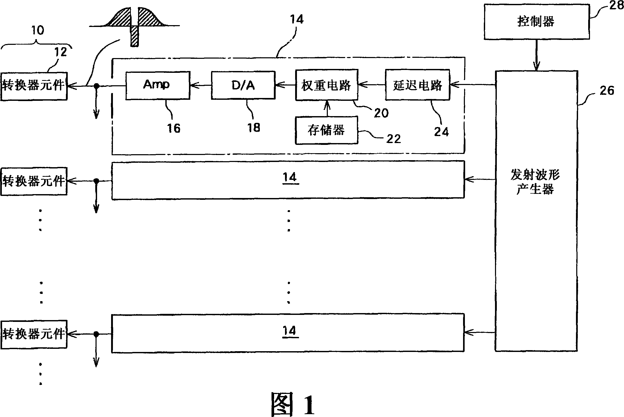
[0038] FIG. 1 shows a block diagram of a transmitter structure in an ultrasonic diagnostic apparatus according to a preferred embodiment of the present invention. This ultrasonic diagnostic apparatus is used in the medical field, and is a device that transmits and receives ultrasonic waves to and from a living body, and forms an ultrasonic image based on the obtained received signal.

[0039] In an ultrasonic probe (not shown), an array converter 10 is provided. The array converter 10 includes a plurality of converter elements 12 . In the present embodiment, a plurality of converter elements arranged one-dimensionally are provided as the array converter 10 . An ultrasonic beam is formed by means of the converter element 12, and the ultrasonic beam is electrically scanned. As for the electric scanning method, various methods such as electric sector scanning ...


PUM


Abstract

An ultrasound diagnosis apparatus having a transmission circuit which generates a transmission signal is provided. The transmission signal corresponds to a combined waveform of a trapezoidal waveform and an impulse-shaped waveform (impulse portion) . In an example transmission signal, a front slope portion, a flat portion, and a rear slope portion exist in a positive polarity side. The impulse portion has a shape which protrudes from an offset level over a base line into an opposite polarity side. Because the center frequency of the trapezoidal waveform is near the DC component, the trapezoidal waveform can substantially be ignored. The impulse portion has a large amplitude, but because the impulse portion exists over both polarities, there is no need to apply a special high voltage countermeasure for each polarity in designing the transmission circuit. A trapezoidal waveform of an opposite polarity may be added in front of the trapezoidal waveform.

Description

technical field [0001] The present invention relates to an ultrasonic diagnostic device, and more particularly to a technique for generating a transmission signal waveform. Background technique [0002] In an ultrasonic diagnostic apparatus, a plurality of transmission signals are supplied to a plurality of transducer elements, and ultrasonic waves are emitted to a living body by the plurality of transducer elements. Each transmission signal is generated by a transmission circuit, and various circuits are known as the transmission circuit (for example, refer to JP 2001-245881 A and JP 2001-087263 A). For example, there are known two circuits in which a transmission pulse is generated by simple switching as a transmission signal, and in which a waveform of positive polarity and a waveform of negative polarity are generated and the waveforms are combined to generate a transmission signal. In recent years, a circuit has been commercialized in which a transmission signal is gen...

Claims


Application Information

Patent Timeline
Patent Type & Authority Applications(China)
IPC IPC(8): A61B8/00
CPCG01S15/102G01S7/52046G01S7/5202
Inventor 曹景文大西隆之纲野和宏小菅正之
Owner HITACHI HEALTHCARE MFG LTD
Why Eureka
Try Eureka