Constant contact side bearing

A side support, rated load technology, applied in the direction of the lateral relative movement between the chassis and the bogie, etc., can solve problems such as movement restrictions, and achieve the effect of improving the side support characteristics and life, long fatigue life, and weight saving.

Active Publication Date: 2008-01-23
AMSTED RAIL CO INC
View PDF2 Cites 2 Cited by
  • Summary
  • Abstract
  • Description
  • Claims
  • Application Information

AI Technical Summary

Problems solved by technology

Most prior art side bearing designs limit the movement of the bearing to about 5 / 6 inch

Method used


Image

  • Constant contact side bearing
  • Constant contact side bearing
  • Constant contact side bearing

Examples


Embodiment Construction

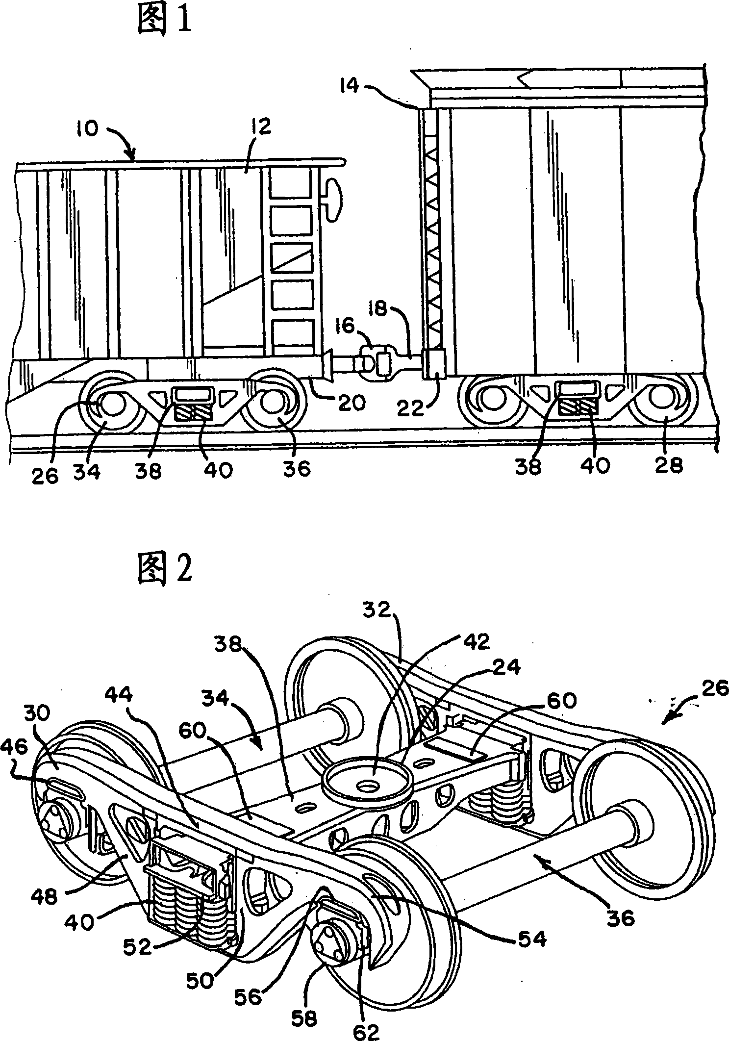
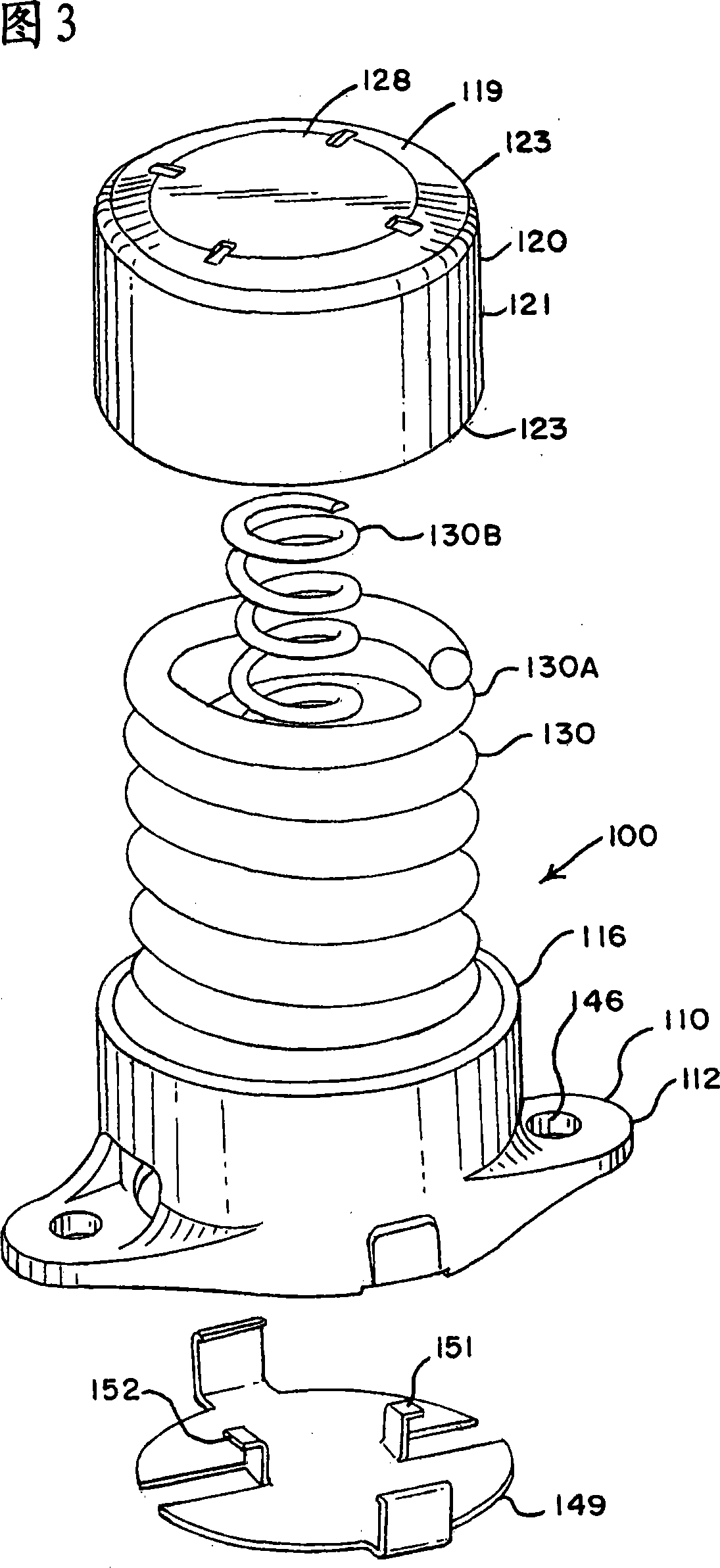
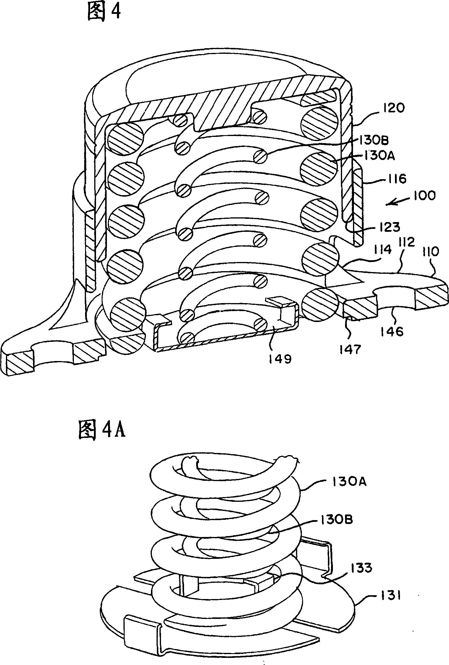
[0038] A first embodiment of the side support of the present invention will be described below with reference to FIGS. 3-11. Side bearing assembly 100 has a main longitudinal axis coincident with the longitudinal axis of the railcar. That is, when the side bearing is mounted on the railcar truck bolster 38, the major axis of the side bearing is perpendicular to the longitudinal axis of the bolster. The side bearing assembly 100 includes as main elements a base 110 , a cap 120 , one or more elastic urging elements 130 (eg, springs or elastomeric elements), and a spring base 131 . In the illustrated exemplary embodiment, there are two springs, an outer spring 130A and an inner spring 130B serving as the propulsion element, each spring may have a different spring constant to provide an overall combined load rating.

[0039] Base 110 is secured to bolster 38 by suitable means. As shown, the base 110 is bolted to the bolster 38 with mounting bolts (not shown) passing through moun...


PUM


Abstract

Long displacement, stable contact side bearings for railcars, through the use of various combinations of features, can provide better handling characteristics for improved trailing and cornering performance. The side support includes a base and a generally cylindrical wall portion extending upwardly from the base. A cup-shaped cap includes a generally circular top and a generally cylindrical wall portion extending downwardly from the top. The cap extends into a wall portion of the base. At least one coil spring is disposed within the base and extends to the underside of the cap.

Description

technical field [0001] The present invention relates to an improved design of side bearings mounted on railcar truck bolsters which allow for long displacements, significant weight savings, improved zigzag and cornering characteristics, and various features for ease of installation. Background technique [0002] In a typical railroad freight car train as shown in FIG. 1, railcars 12,14 are connected end-to-end by connectors 16,18. Each of the connectors 16, 18 is received in a draw beam 20, 22 of a respective respective vehicle, along with a hydraulic damper or traction gear assembly (not shown). The drawbeams 20 , 22 are provided at the ends of the railcar center beams and include center plates seated in the center plate bowls of the rail car trucks 26 , 28 . [0003] As best shown in FIG. 2, each typical rail car truck 26 includes a pair of side frames 30,32 supported on wheel sets 34,265. The bolster 38 extends between and bears on springs 40 mounted on the side frames....

Claims


Application Information

Patent Timeline
Patent Type & Authority Applications(China)
IPC IPC(8): B61F5/06
CPCB61F5/14
Inventor B·约翰斯通D·J·施奈尔斯J·M·鲁拜克J·P·莫纳科
Owner AMSTED RAIL CO INC
Why Eureka
Try Eureka