
Method for manufacturing array substrate

Inactive Publication Date: 2017-07-13
WUHAN CHINA STAR OPTOELECTRONICS TECH CO LTD
View PDF0 Cites 1 Cited by
  • Summary
  • Abstract
  • Description
  • Claims
  • Application Information

AI Technical Summary

Benefits of technology

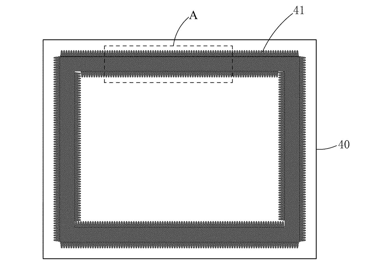
The present invention provides a method for manufacturing an array substrate that reduces side taper of a groove formed in a circumferential area of a planarization layer, making the slope thereof less steep and lowered, in order to prevent shorting of signal lines caused by residues of metal or ITO in a subsequent operation and thereby increasing product yield. This method involves using a planarization layer mask with taper modification patterns to form grooves in the planarization layer with reduced side taper. Additionally, this method allows for the formation of a pixel electrode and a touch sensing line without leaving residues of the oxide conductive layer or metal layer in the grooves, thereby increasing product yield.

Problems solved by technology

However, this causes a technical problem.
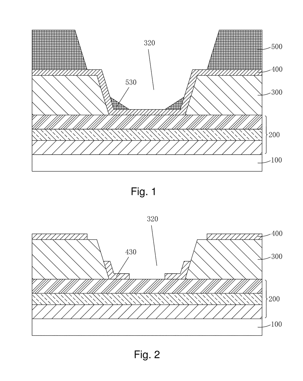
This leads to a great amount of indium tin oxide (ITO) left in the groove in a subsequent operation related to an ITO pixel electrode and such ITO would cause undesired shorting of the signal lines, resulting in poor displaying.
Shorting of the signal lines caused by ITO is an issue that small- and medium-sized panels face.
Similarly, for an array substrate involving an in-cell touch structure, metal residue of M3 (the metal layer where a touch sensing line Rx is located) would occur, leading to incorrect touch signal and thus affecting product quality.

Method used


Image

  • Method for manufacturing array substrate
  • Method for manufacturing array substrate
  • Method for manufacturing array substrate

Examples


Embodiment Construction

[0035]To further expound the technical solution adopted in the present invention and the advantages thereof, a detailed description is given to a preferred embodiment of the present invention with reference to the attached drawings.

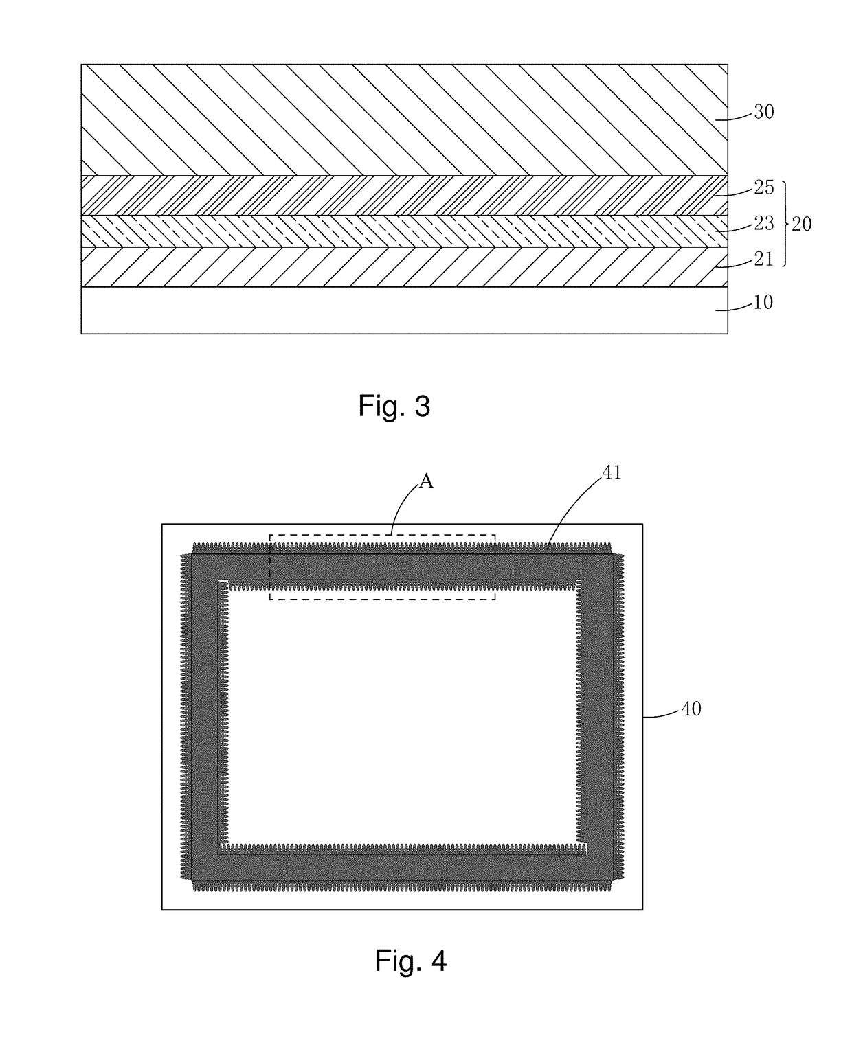
[0036]Referring to FIGS. 3-12, the present invention provides a method for manufacturing an array substrate, which comprises the following steps:

[0037]Step 1: as shown in FIG. 3, providing a base plate 10, forming a thin-film transistor (TFT) layer 20 on the base plate 10, and then coating an organic photoresist material on the TFT layer 20 to form a planarization layer 30.

[0038]Specifically, the base plate 10 is a transparent plate, and is preferably a glass plate.

[0039]Specifically, as shown in FIG. 3, the TFT layer 20 comprises a buffer layer 21, a gate insulation layer 23, and an interlayer dielectric layer 25. Further, the TFT layer 20 also comprises an active layer, a gate electrode, and source / drain electrodes arranged among the buffer layer 21, th...


PUM


Abstract

Provided is a method for manufacturing an array substrate, in which a planarization layer mask includes a strip pattern that is provided for forming a groove and has two opposite sides along which taper modification patterns are provided so as to reduce taper of a groove formed in a planarization layer, making a slope thereof less steep, thereby preventing shorting of signal lines caused by residues of metal or ITO in a subsequent operation and thus increasing product yield. For the groove associated portion of an array substrate involving an in-cell touch structure, there is no need to change line for the touch sensing lines so as to lower down the difficulty of the operation and increase product yield.

Description

BACKGROUND OF THE INVENTION[0001]1. Field of the Invention[0002]The present invention relates to the field of display technology, and in particular to a method for manufacturing an array substrate.[0003]2. The Related Arts[0004]With the progress of the display technology, flat panel display devices, such as liquid crystal displays (LCDs), due to various advantages, such as high image quality, low power consumption, thin device body, and wide range of applications, have been widely used in all sorts of consumer electronic products, including mobile phones, televisions, personal digital assistants (PDAs), digital cameras, notebook computers, and desktop computers, making them the main stream of display devices.[0005]Most of the liquid crystal display devices that are currently available in the market are backlighting LCDs, which comprise a liquid crystal display panel and a backlight module. The working principle of the liquid crystal display panel is that liquid crystal molecules are...

Claims


Application Information

Patent Timeline
IPC IPC(8): H01L27/12G02F1/1339G02F1/1333G02F1/1368H01L21/311G06F3/041H01L21/77
CPCH01L27/1288H01L21/31144G06F3/0412G06F2203/04103G02F1/1368G02F1/1339G02F1/13338G02F1/136295H01L27/1259G02F2202/28G02F1/133357G02F1/133388G02F1/13606G02F1/136236H01L27/1248
Inventor LIU, YUANFUTANG, FUHSIUNG
Owner WUHAN CHINA STAR OPTOELECTRONICS TECH CO LTD
Learn More