A wet magnetic separator and its control method
A wet magnetic separator and magnetic separation technology, applied in chemical instruments and methods, magnetic separation, solid separation, etc., can solve problems affecting work efficiency, production line shutdown, and complex magnetic system installation structure, etc., to achieve broad application prospects and improve The effect of operating efficiency
- Summary
- Abstract
- Description
- Claims
- Application Information
AI Technical Summary
Problems solved by technology
Method used
Image
Examples
Embodiment 1
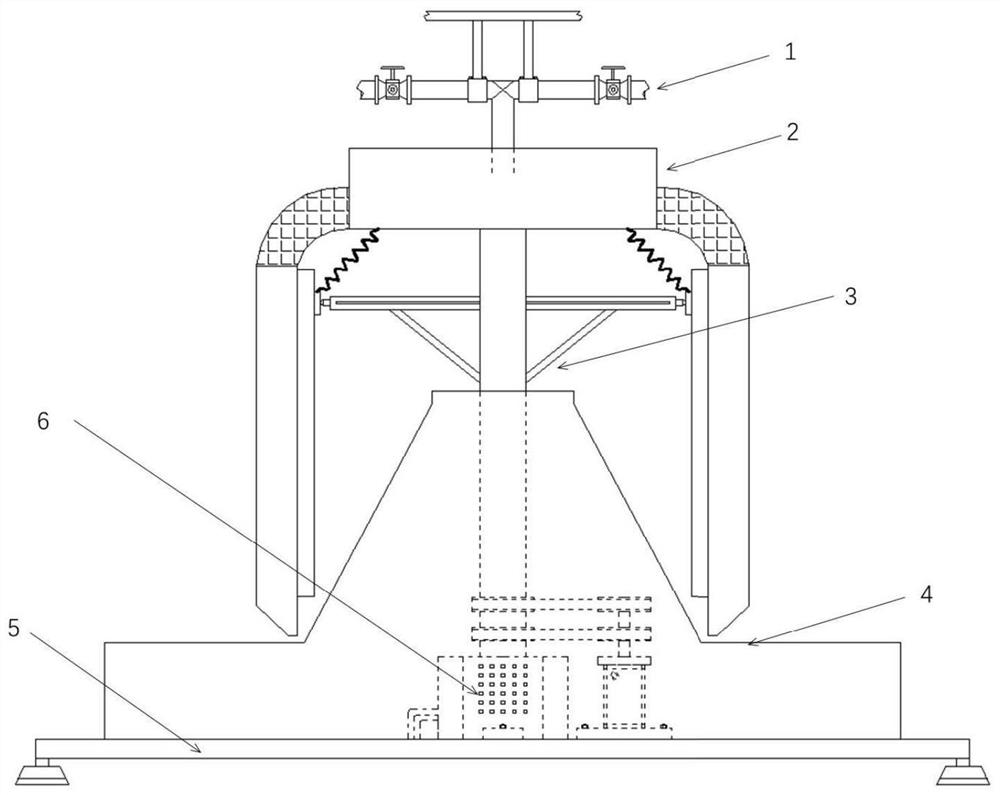
[0038] Reference attached figure 1 , the magnetic separator includes a feeding part 1 , a sorting part 2 , a power part 3 , an annular collecting part 4 , a supporting part 5 and a power supply part 6 .
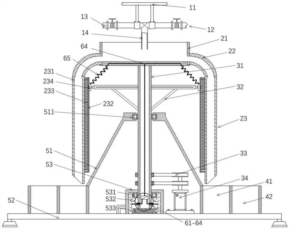
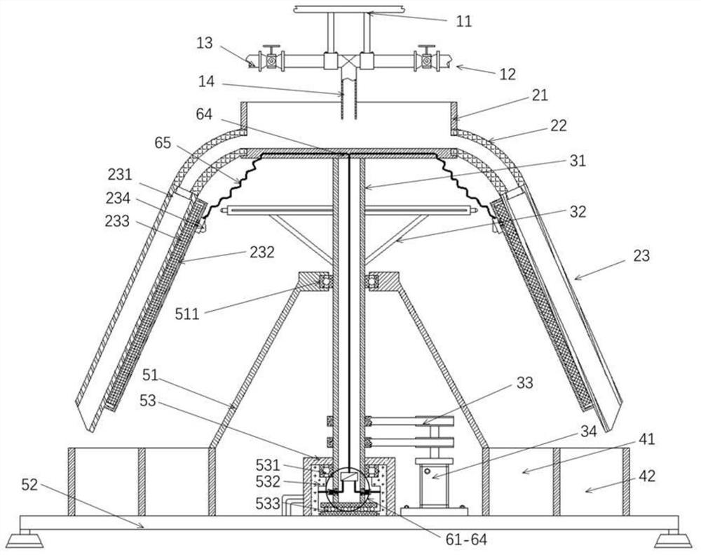
[0039] Reference attached figure 2 , the magnetic separator is a wet magnetic separator, which is used for magnetic separation of slurry mixed with magnetic materials, and its feeding part 1 has an upper bracket 11, a flushing pipe 12, a slurry pipe 13 and a discharge pipe 14; the upper part The support 11 is arranged on the top of the whole wet magnetic separator, and the flushing pipe 12, the slurry pipe 13 and the discharge pipe 14 are fixed by the upper support 11; the flushing pipe 12 and the slurry pipe 13 are provided with respective valves, and the valves can be It is a manual valve and can also be an electric control valve; clean water for flushing is passed into the flushing pipe 12, and the prepared slurry to be magnetically separated is passed into the slurry pi...
Embodiment 2
[0051] Reference attached Figure 5-6 , the magnetic separator of this embodiment is an energy-saving wet magnetic separator, which has carried out further energy-saving transformation on the basis of the first embodiment, and the transmission mechanism 33 and the motor 34 in the power part 3 in the first embodiment are removed , and the flushing pipe 12 is specifically divided into a low-pressure flushing pipe 121 and a high-pressure flushing pipe 122. Both the low-pressure flushing pipe 121 and the high-pressure flushing pipe 122 are connected to the discharge pipe 14. The above-mentioned valve can be a manual valve or an electric control valve. What passes into the low-pressure flushing pipe 121 is low-pressure clear water, and what passes into the high-pressure flushing pipe 122 is high-pressure clear water; What passes into the pipe 13 is a high-pressure slurry; several discharge necks 141 are installed on the outlet of the discharge pipe 14 for ejecting liquid.
[0052]...
Embodiment 3
[0060] Reference attached Figure 7-9 The magnetic separator in this embodiment is a dry magnetic separator, which is used for the magnetic separation of dry powdery materials. It has carried out adaptive transformation on the basis of the first embodiment, and the punching part of the feeding part 1 in the first embodiment is The water pipe 12, the slurry pipe 13, and the discharge pipe 14 are removed, and a lower hopper 15 is installed on the upper bracket 11 of the feeding part 1, and the outlet of the lower hopper 15 corresponds to the upper opening of the receiving box 21 in the sorting part 2; A material distributing cone 212 is arranged in the material receiving box 21 , and the conical top of the material distributing cone 212 is directly facing the discharge port of the lower hopper 15 for guiding the falling material to slide to the sorting part 2 .
[0061] Since the material to be magnetically separated is a dry powder material, in order to improve the sorting effi...
PUM
 Abstract
Description
Claims
Application Information
 - R&D
- Intellectual Property
- Life Sciences
- Materials
- Tech Scout
- Unparalleled Data Quality
- Higher Quality Content
- 60% Fewer Hallucinations
Browse by: Latest US Patents, China's latest patents, Technical Efficacy Thesaurus, Application Domain, Technology Topic, Popular Technical Reports.
© 2025 PatSnap. All rights reserved.Legal|Privacy policy|Modern Slavery Act Transparency Statement|Sitemap|About US| Contact US: help@patsnap.com


