Supercharge Your Innovation With Domain-Expert AI Agents!

Method for manufacturing watercraft commutation tube

A manufacturing method and catheter technology, which is applied in shipbuilding, manufacturing tools, ship parts, etc., can solve the problems of long manufacturing hours, high cost, and low precision, and achieve the effects of saving manufacturing time, improving production efficiency, and speeding up construction

Active Publication Date: 2011-06-15
HUDONG ZHONGHUA SHIPBUILDINGGROUP
View PDF0 Cites 0 Cited by
  • Summary
  • Abstract
  • Description
  • Claims
  • Application Information

AI Technical Summary

Problems solved by technology

[0006] In the above-mentioned prior art, because the tire frame used is not a solid body, the deformation during linear laying, positioning and welding is difficult to control
In the prior art, the inner shell is used as the base surface to manufacture rectifying ducts, and there are still disadvantages such as difficulty in laying tire frames, low precision, long manufacturing hours, and high cost.

Method used


Image

  • Method for manufacturing watercraft commutation tube
  • Method for manufacturing watercraft commutation tube
  • Method for manufacturing watercraft commutation tube

Examples


Embodiment 1

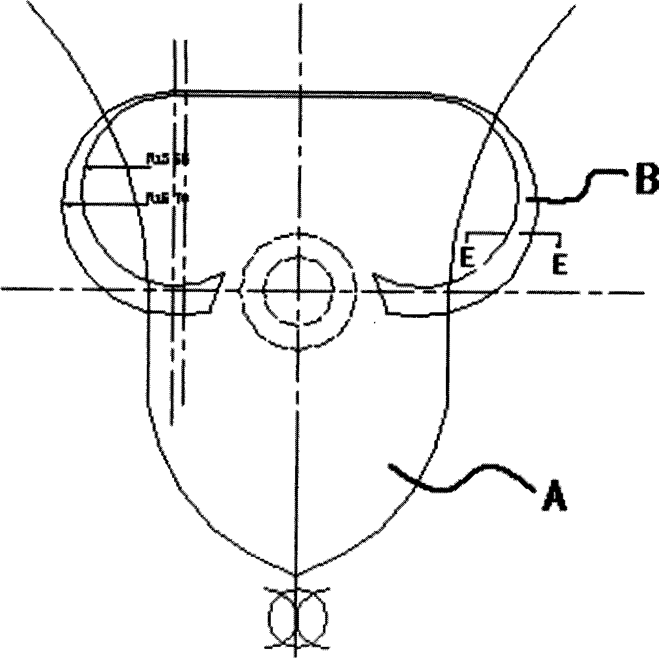
[0029] The practical application of the method of the present invention will be specifically described below with the manufacture of a rectifying duct on a 50,000-ton ship.

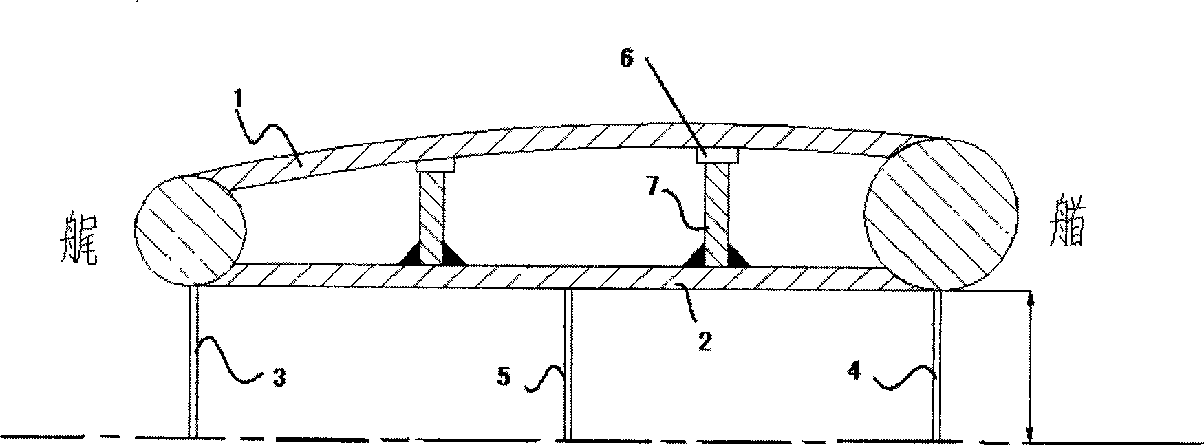
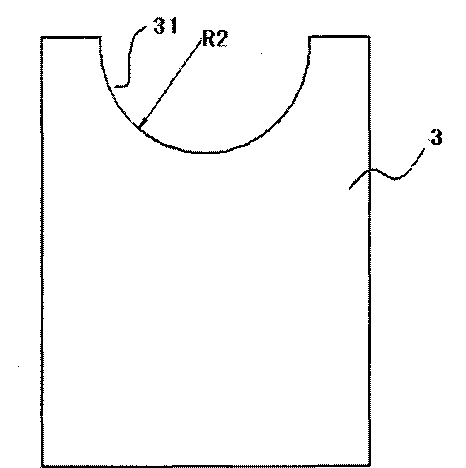
[0030] The rectifying duct includes an inner shell plate 1 and an outer shell plate 2, wherein the outer shell plate 2 is a semi-conical frustum shape, the radius of one end is R1=1570mm, and the radius of the other end is R2=1355mm. The inner shell plate 1 is formed by a plurality of blocks. The inner shell plate 1 and the outer shell plate 2 are fixed by a rib plate 7, one end of the rib plate 7 is welded to the scribed line position in the outer shell plate 2, and the other end is fixed with a plurality of rib plates 7, one end of the plurality of rib plates 7 After being fixed on the outer shell plate 2 , the end contacting with the inner shell plate 1 has the same line shape as the inner shell plate 1 . The inner shell constituent plates are welded and fixed at the upper ends of the plurality of rib ...


PUM

PropertyMeasurementUnit
lengthaaaaaaaaaa
widthaaaaaaaaaa
radiusaaaaaaaaaa

Abstract

The invention relates to a manufacture method of a ship rectification duct, which comprises the following steps: (1) manufacturing a bow fetal board and processing a first breach and manufacturing a bow fetal board and processing a second breach which is located as a shaped grid; (2) arranging the base level of the shaped grid and fixing the lowest point and ensuring the level; (3) assembling an outside casing plate and rolling a semi-circled table for the outside casing plate; (4) providing the outside casing plates on the internal frames of the first breach and the second breach; (5) rulingin the outside casing plate and installing a knee plate distributed horizontally and vertically; (6) installing an inner casing composition plate on the knee plate and welding the composition plate into inner casing plate and completing the manufacture of the rectification duct after checking and adjusting. The manufacture method of the rectification duct of the invention can easily control the deformation of the whole manufacture method of the rectification duct, ensures the accuracy of inner and outer linearity of the rectification duct, improves the production efficiency, saves time and speeds up the construction of the whole ship.

Description

technical field [0001] The invention relates to ship construction, in particular to a method for manufacturing a ship rectifying duct. Background technique [0002] The fairing duct is an important energy-saving component on the ship, which can improve the water flow at the propeller during the propulsion process of the ship, so as to reduce energy consumption and increase thrust. [0003] The fairing duct is composed of a set of circular frustum-shaped double shells, which are installed at the stern of the ship, located at the outlet of the propeller, with one on each side, such as figure 1 shown, figure 1 It is a schematic diagram of the installation position of the rectifier conduit. [0004] The main function of the rectifier duct is to improve the water flow state, and it is an important ship propulsion energy-saving device. please see figure 2 ,Yes figure 1 E-E sectional view of the middle rectifying duct. It can be seen from the figure that the rectifying duct ...

Claims


Application Information

Patent Timeline
Patent Type & Authority Patents(China)
IPC IPC(8): B63B9/06B23K31/00
CPCB63H1/28
Inventor 姚银弟徐兴智周飞陈建中
Owner HUDONG ZHONGHUA SHIPBUILDINGGROUP
Features
  • R&D
  • Intellectual Property
  • Life Sciences
  • Materials
  • Tech Scout
  • Unparalleled Data Quality
  • Higher Quality Content
  • 60% Fewer Hallucinations
Learn More