Zoom lens system, imaging apparatus, method for vibration reduction, and method for varying focal length

A zoom lens and focal length technology, applied in the field of zoom systems, can solve the problems of insufficient zoom ratio and wide viewing angle.

Inactive Publication Date: 2008-01-23
NIKON CORP
View PDF3 Cites 15 Cited by
  • Summary
  • Abstract
  • Description
  • Claims
  • Application Information

AI Technical Summary

Problems solved by technology

[0006] However, due to its small zoom ratio, this zoom lens system is not enough to meet the needs of having a large zoom ratio
Also, due to the narrow viewing angle in the wide-angle state, this zoom lens system is insufficient to meet the needs of having a wide viewing angle

Method used


Image

  • Zoom lens system, imaging apparatus, method for vibration reduction, and method for varying focal length
  • Zoom lens system, imaging apparatus, method for vibration reduction, and method for varying focal length
  • Zoom lens system, imaging apparatus, method for vibration reduction, and method for varying focal length

Examples


no. 1 example

[0049] The zoom lens system, imaging apparatus, method for vibration reduction, and method for changing the focal length according to the first embodiment are explained below.

[0050] The zoom lens system according to the first embodiment includes, in order from the object: a first lens group having positive refractive power, a second lens group having negative refractive power, a third lens group having positive refractive power, and a third lens group having positive refractive power. Ability of the fourth lens group. When zooming from the wide-angle end state to the telephoto end state, the distance between the first lens group and the second lens group increases, the distance between the second lens group and the third lens group decreases, and the first lens group The distance between the third lens group and the fourth lens group varies. In order from the object, the third lens group includes a front lens group having positive refractive power, and a rear lens group ha...

example 1

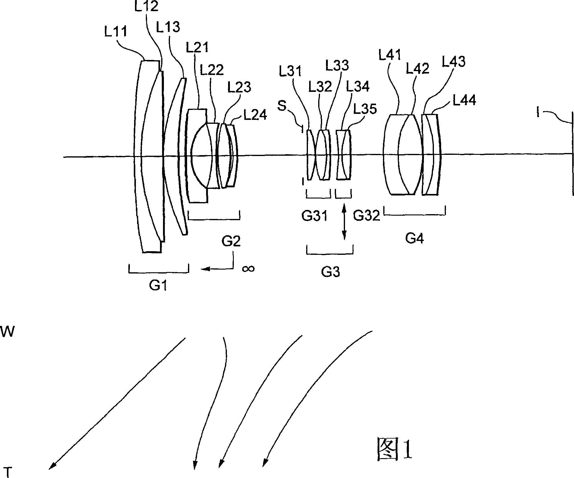
[0112] FIG. 1 is a schematic diagram showing a lens configuration of a zoom lens system according to Example 1 of the first embodiment together with a zoom locus of each lens group.

[0113] The zoom lens system according to Example 1 includes, in order from the object: a first lens group G1 having positive refractive power, a second lens group G2 having negative refractive power, a third lens group G3 having positive refractive power, and a lens group having The fourth lens group G4 with positive refractive power.

[0114] The first lens group G1 includes, in order from the object: a cemented lens composed of a negative meniscus lens L11 with a convex surface facing the object cemented with a positive meniscus lens L12 with a convex surface facing the object, and a lens with a convex surface facing the object. The convex surface of the positive meniscus L13.

[0115] This second lens group G2 includes, in order from the object: a negative meniscus lens L21 having a convex su...

example 2

[0222] 5 is a schematic diagram showing a lens structure of a zoom lens system according to Example 2 of the first embodiment together with a zoom locus of each lens group.

[0223] The zoom lens system according to Example 2 includes, in order from the object: a first lens group G1 with positive refractive power, a second lens group G2 with negative refractive power, a third lens group G3 with positive refractive power, and a lens group with positive refractive power. Refractive power of the fourth lens group G4.

[0224] The first lens group G1 includes, in order from the object: a cemented lens composed of a negative meniscus lens L11 with a convex surface facing the object cemented with a positive meniscus lens L12 with a convex surface facing the object, and a lens with a convex surface facing the object. The convex surface of the positive meniscus L13.

[0225] This second lens group G2 includes, in order from the object: a negative meniscus lens L21 having a convex sur...


PUM


Abstract

A telephoto-type of zoom includes, in order from the object, a first lens group having positive power, a second lens group having negative power, a third lens group having positive power, and a fourth lens group having positive power. Upon zooming from wide-angle end to telephoto end, the distance between the first and the second lens groups increases, the distance between the second and the third lens groups decreases, and the distance between the third and the fourth lens groups varies. The third lens group consists of a front group and a rear group. Vibration reduction is carried out by moving only the rear group perpendicularly to the optical axis.

Description

[0001] The contents of the following prior applications are hereby incorporated by reference: [0002] Japanese Patent Application No. 2006-198453 filed on July 20, 2006; and [0003] Japanese Patent Application No. 2006-340332 filed on December 18, 2006. technical field [0004] The present invention relates to a zoom system, an imaging device, a vibration reduction method, and a method of changing the focal length of a zoom lens system. Background technique [0005] A zoom lens system having a vibration reduction function has been proposed in, for example, Japanese Patent Application Laid-Open No. 2001-166208. [0006] However, due to its small zoom ratio, this zoom lens system is insufficient to have a large zoom ratio. Also, due to the narrow viewing angle in the wide-angle state, the zoom lens system is insufficient to have a wide viewing angle. Contents of the invention [0007] The present invention is proposed in view of the above problems, and the purpose of th...

Claims


Application Information

Patent Timeline
Patent Type & Authority Applications(China)
IPC IPC(8): G02B15/16G02B13/00G02B9/34
Inventor 伊藤智希
Owner NIKON CORP
Why Eureka
Try Eureka