Automatization test approach and system

A technology for automated testing and system under test, applied in the field of testing, can solve problems such as manual intervention, cumbersome configuration, and impact

Inactive Publication Date: 2008-01-23
RUIJIE NETWORKS CO LTD
View PDF0 Cites 29 Cited by
  • Summary
  • Abstract
  • Description
  • Claims
  • Application Information

AI Technical Summary

Problems solved by technology

[0010] (1) Each automated test program or script has its own configuration file, and each configuration file needs to be configured during the test; when there are many test programs or scripts, the workload is heavy and the configuration is cumbersome, and the configuration files in each configuration file Some configuration information is repeated, such as the IP address of the data network tester, the port used, etc.;
[0011] (2) Each automated test program or script has different requirements for the test topology. For example, test program 1 only tests a single device under test, and test program 2 needs to test two devices under test at the same time. Since there is no unified test topology Definition, which requires manual test topology transformation, resulting in that each test script cannot be executed sequentially, and the entire test process requires manual intervention;
[0012] (3) Since the test topology of each test program or script may be a part of the actual test topology, testers can manually judge the actual test topology and extract part of the topology to complete the parameter configuration of each test program or script. However, this requires test executives to be familiar with the test topology of each test program or script, which increases the requirements for testers. In addition, the test topology that is not used in the entire test topology may have an impact on the currently used test topology

Method used


Image

  • Automatization test approach and system
  • Automatization test approach and system
  • Automatization test approach and system

Examples


Embodiment Construction

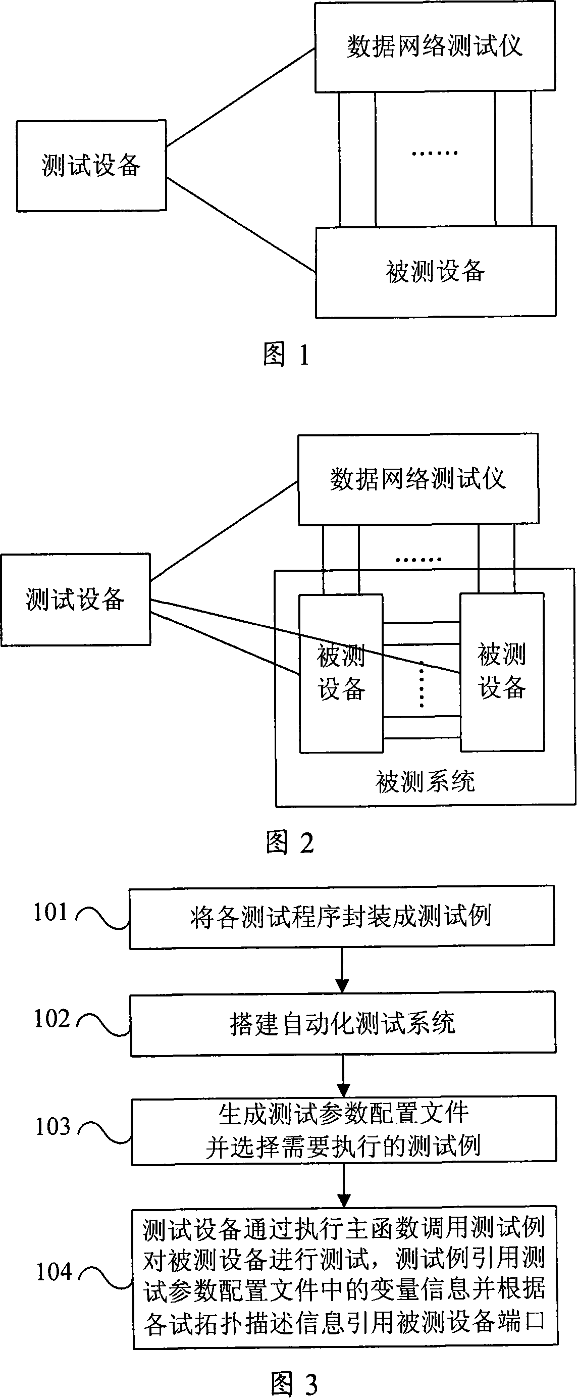
[0032] As shown in FIG. 2 , it is a schematic structural diagram of an embodiment of the automated testing system of the present invention. The test equipment and the data network tester communicate through the Ethernet to control the corresponding ports of the data network tester to send and receive test frames. The test port of the data network tester is connected to the corresponding port of each device under test to realize the sending and receiving of test frames. The system under test consists of one or more devices under test. The test equipment configures the system under test, controls the equipment under test and the data network tester, and tests the system under test by executing the test case encapsulated by the test program and calling the test program.

[0033] As shown in Figure 3, it is a flowchart of an embodiment of the automated testing method of the present invention, including the following steps:

[0034] Step 101, encapsulating the test program into a...


PUM


Abstract

The present invention relates to an automated testing method. The present invention comprises: the testing program is packed into a test case, which is unitedly invoked by the main function; an automated testing system is built; the testing system comprises a testing equipment, a data network tester and a tested system, and the tested system comprises at least a tested equipment; a testing parameter configuration file is generated and a test case to be executed is selected, the information recorded in the testing configuration file comprises a parameter configuration variable information and a testing topology description information; the testing equipment invokes the selected test case through the execution of the main function, the tested system is tested, and the test case quotes the variable information in the testing parameter configuration file and quotes the tested equipment interface according to the testing topology description information. The present invention also relates to an automated testing system. The present invention realizes the united configuration of the parameter, and a plurality of test case sequences can be executed without the frequent conversion of the testing topology.

Description

technical field [0001] The invention relates to testing technology, in particular to an automatic testing method and system capable of realizing unified parameter configuration and sequentially executing multiple test cases without frequent test topology transformation. Background technique [0002] Automated testing is to run the automated testing program on the testing equipment (such as personal computer PC). The automated testing program configures the tested equipment through the serial port (Com) or remote login (Telnet), and controls the data network tester to send and receive test frames. , and complete the automatic acquisition and judgment of test results, and finally obtain the test result of passing or failing the script. [0003] As shown in FIG. 1 , it is a schematic diagram of a test topology of an existing single device under test. [0004] The device under test can be a switch, router or other products under test. [0005] The data network tester is a stan...

Claims


Application Information

Patent Timeline
Patent Type & Authority Applications(China)
IPC IPC(8): H04L12/28H04L12/24
Inventor 林奇
Owner RUIJIE NETWORKS CO LTD
Why Eureka
Try Eureka