Mechanical tensioning device for dowm pressing

A tensioning device, mechanical technology, used in mechanical equipment, transmissions, belts/chains/gears, etc.

Inactive Publication Date: 2008-01-30
DAIDO KOGYO CO LTD
View PDF3 Cites 7 Cited by
  • Summary
  • Abstract
  • Description
  • Claims
  • Application Information

AI Technical Summary

Problems solved by technology

However, since the bottom surface of the rotary sleeve which should be able to withstand the reaction force of the chain is on the upper side, the self-weight and the vibration inertial force generated b

Method used


Image

  • Mechanical tensioning device for dowm pressing
  • Mechanical tensioning device for dowm pressing
  • Mechanical tensioning device for dowm pressing

Examples


Embodiment Construction

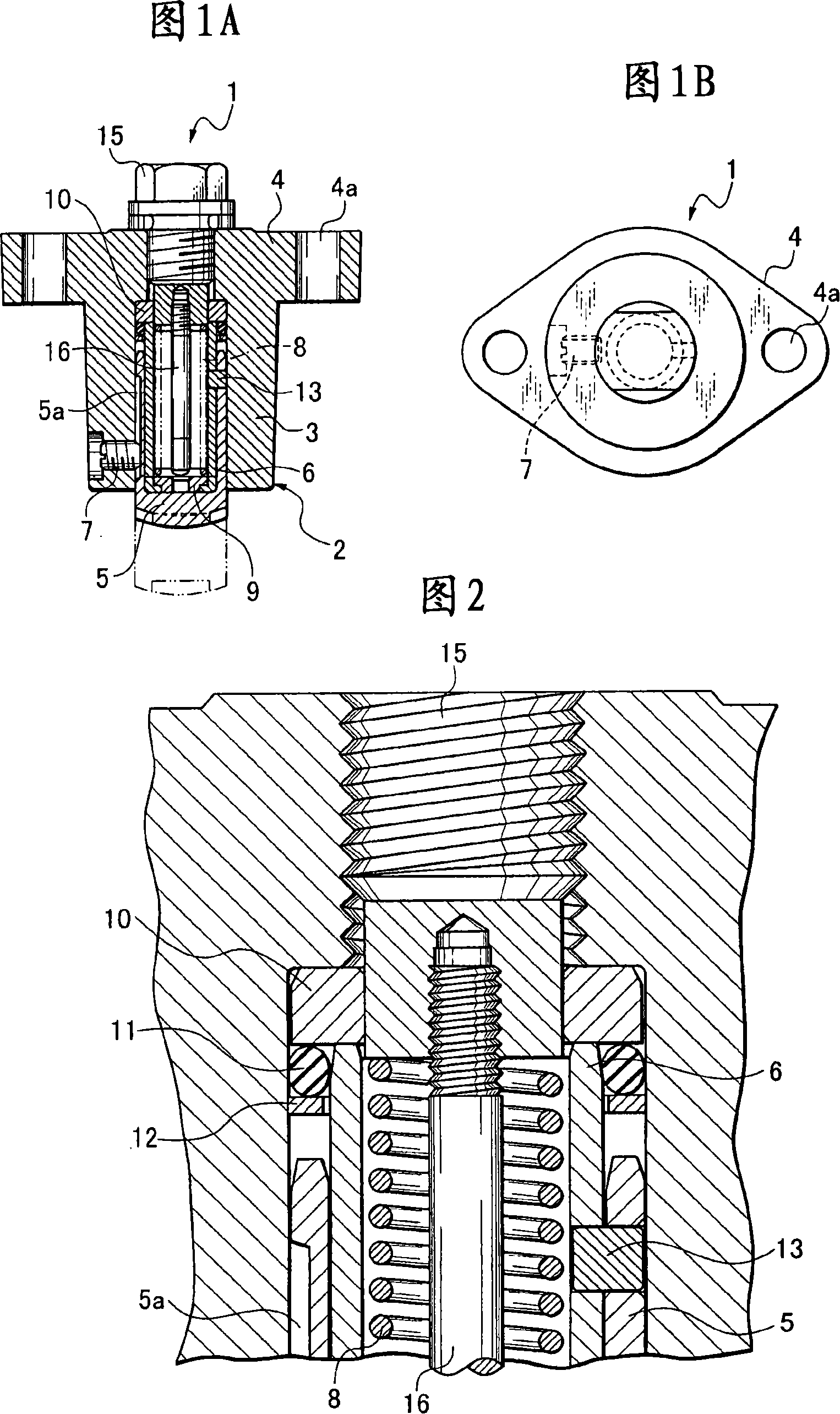
[0020] 1A and 1B show a mechanical tensioner for pressing down according to an embodiment of the present invention, which has a die-cast cylindrical main body 2 made of a cylindrical cylinder 3 and a boss for mounting on an engine block. An edge-shaped mounting part 4 is formed. A cylindrical plunger 5 having a head is slidably accommodated in the cylinder 3 , and a cylindrical pawl drive cylinder 6 is engaged in the plunger 5 . The main body 2 is attached to the engine block through bolt holes 4 a formed in the attachment portion 4 .

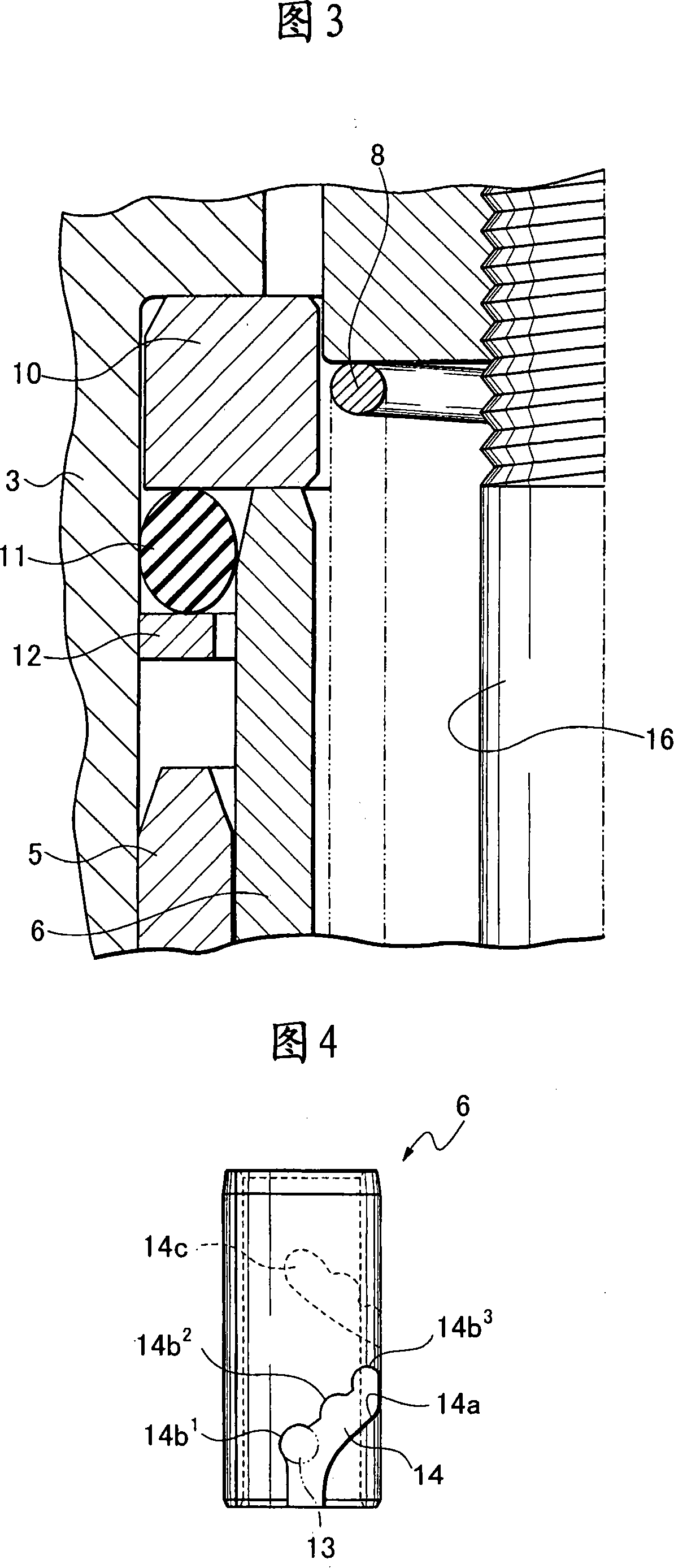
[0021] A notch 5a is formed on a part of the outer surface of the cylindrical portion of the plunger 5, and a detent pin 7 is screwed into a threaded hole penetrating through the side wall of the cylinder 3, and is rotatably restricted by the detent pin 7. Therefore, the plunger 5 can slide without turning and protrudes from the cylinder 3 . In addition, a columnar claw pin 13 is fitted and fixed in a hole penetrating through a part of the ou...


PUM


Abstract

The present invention provides a down pressing mechanical tension device which adopts a simple conformation of the handle ratchet wheel style of the rotating sleeve, and the mechanical tension device pushes and presses the upside crotch of the chain which is coiled and suspended between the sprocket wheels and exerts a definite fastening force; wherein: the main body is formed with a cylinder in which the cylindrical plunger piston is accommodated with the mode that the plunger piston can move freely at the up-and-lower direction but can not revolved, a pawl activating cylinder in the plunger piston with the mode that the pawl activating cylinder will not drop but can freely fitted rotatably, and a return spring which accommodates the exerted force to the plunger piston in the pawl activating cylinder. A helical groove is arranged at the surrounding wall of the pawl activating cylinder and a plurality of junctions are formed along the helical groove at the same time. The junction which is jointed at the helical groove that forms at the surrounding of the pawl activating cylinder prevents the retreating of the plunger piston when the plunger piston fixes the claw pin and the load in the reverse direction acts on the head of the plunger piston.

Description

technical field [0001] The present invention relates to a mechanical tensioner for preventing slack in transmission chains. Background technique [0002] A hydraulic tensioner is generally used as a tensioning device for preventing chain vibration caused by elongation and excessive tension caused by vibration, but such as the engine of a small and medium-sized motorcycle, it cannot When supplying oil exclusively for the tensioner, a mechanical tensioner utilizing spring force is used. [0003] Generally, in such a tensioner, a spring biases a push rod movably held to a fixed portion (main body) to push the chain in the tensioning direction. In such a tensioner, in order for the plunger not to move in the backward direction due to lower chain tension when a load in the return direction acts on the chain, a strong resistance to the force of movement in the backward direction of the push rod is required. [0004] In order to obtain such a backward preventing resistance, there...

Claims


Application Information

Patent Timeline
IPC IPC(8): F16H7/08
Inventor 山田昭
Owner DAIDO KOGYO CO LTD
Why Eureka
Try Eureka