High-temperature continuously temperature measuring system and manufacturing method of temperature measurement pipe

A manufacturing method and a temperature measuring tube technology, which are applied to electric radiation detectors and other directions, can solve the problems of low temperature measurement accuracy, complicated and cumbersome processes, thermal shock rupture of the inner tube, etc., and achieve improved measurement accuracy, good continuous temperature measurement, The effect of structural stability

Inactive Publication Date: 2010-08-04
FOCUSED PHOTONICS
View PDF3 Cites 0 Cited by
  • Summary
  • Abstract
  • Description
  • Claims
  • Application Information

AI Technical Summary

Problems solved by technology

However, the structure of this device determines that the thermal conductivity is relatively poor, so there are problems such as long response time and low temperature measurement accuracy, and the cost of the temperature measuring tube composed of the inner and outer tubes is relatively high. In the environment, it is more likely to cause thermal shock rupture of the inner tube and fail to work
In the manufacturing process of this kind of device, the outer tube and the inner tube need to be processed separately, and then the inner and outer tubes are assembled more complicatedly, and the process is complicated and cumbersome.

Method used


Image

  • High-temperature continuously temperature measuring system and manufacturing method of temperature measurement pipe
  • High-temperature continuously temperature measuring system and manufacturing method of temperature measurement pipe
  • High-temperature continuously temperature measuring system and manufacturing method of temperature measurement pipe

Examples


Embodiment 1

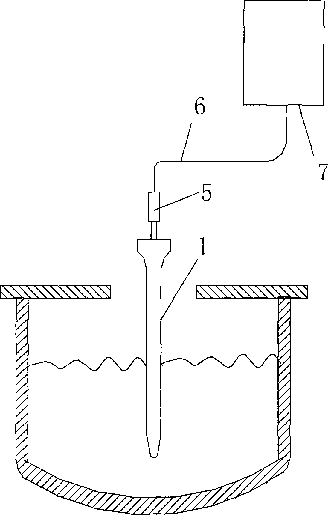
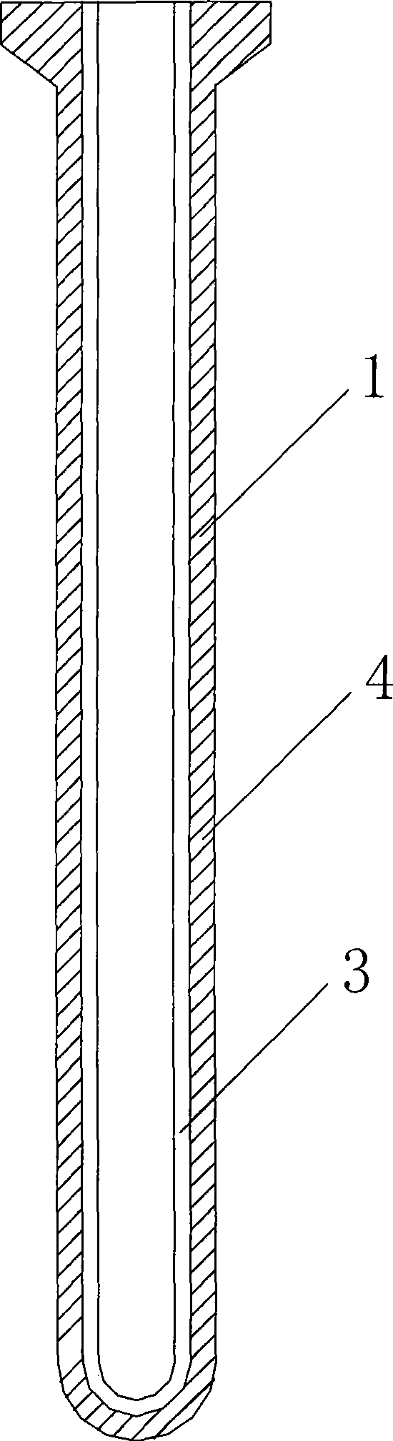
[0036] Such as figure 1 , 2 As shown, the following part of this embodiment describes a high-temperature continuous temperature measurement system: including a temperature measuring tube 1, a light receiving probe 5, a cable 6 and a signal analyzer 7, and the temperature measuring tube 1 includes an inner layer 3 sintered together and the outer layer 4, the outer layer 4 is composed of conventional aluminum-carbon materials, and conventional zirconium-carbon materials or magnesium-carbon materials can also be used. The inner layer 3 is a carbon-free and silicon-free layer, and the formula and weight percentage of the carbon-free and silicon-free layer are respectively For: Magnesium Aluminum Spinel 85%, Light Burnt AL 2 o 3 2%, graphite 1%, boron carbide 5%, clay powder 1%, phenolic resin 6%. The inner layer 3 has a thickness of 4 mm. The temperature measuring tube 1 is connected with the light receiving probe 5 , and the light receiving probe 5 and the signal analyzer 7 ...

Embodiment 2

[0040] Such as Figure 5 As shown, the parts other than the temperature measuring tube 1 of this embodiment are completely the same as those of Embodiment 1, and will not be repeated here. The difference lies in the temperature measuring tube 1. The temperature measuring tube 1 includes an inner layer 3 and an outer layer 4 that are sintered together. The outer layer 4 is composed of conventional aluminum carbon materials, and conventional zirconium carbon materials or magnesium carbon materials can also be used. The inner layer 3 is a carbon-free and silicon-free layer. The formula and weight percentage of the carbon-free and silicon-free layer are: 72% magnesium aluminum spinel, 15% lightly burned AL2O3, 5% graphite, 1% clay, 2% Feldspar, 5% phenolic resin. The inner layer 3 has a thickness of 5 mm. The inner layer 3 and the outer layer 4 are not equal in length, and the length of the inner layer 3 is less than the length of the outer layer 4, because according to known te...

Embodiment 3

[0044]The structure of the high-temperature continuous temperature measurement system of this embodiment is the same as that of the high-temperature continuous temperature measurement system of Embodiment 1, and the difference from Embodiment 1 is that the formula and weight percentage of the inner layer of this embodiment are: 70% magnesium-aluminum spinel Stone, 15% lightly burned AL 2 o 3 , 4% graphite, 2% boron carbide, 2% glass frit, 1% feldspar, 6% phenolic resin. The inner layer 3 has a thickness of 3 mm.

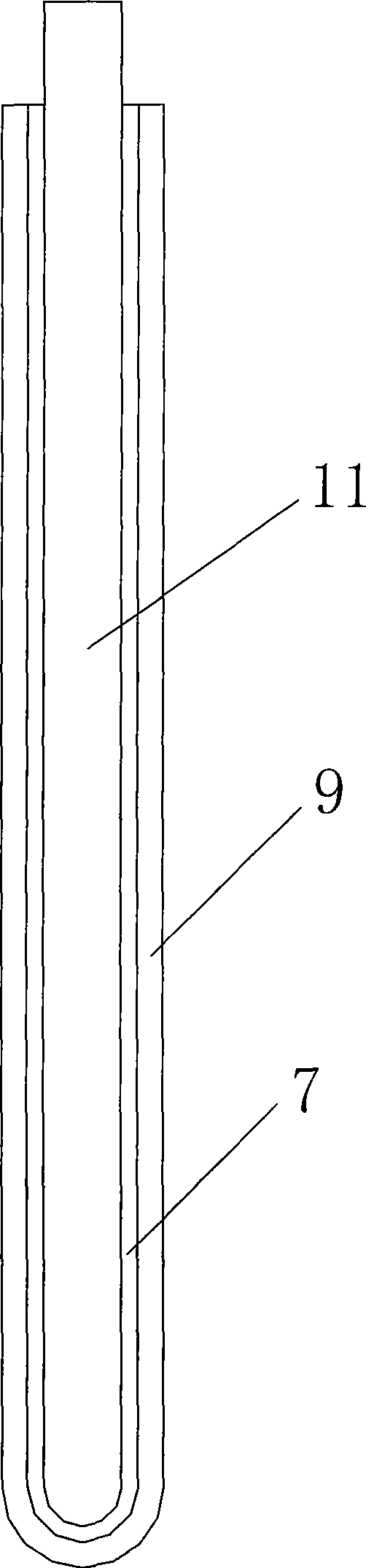
[0045] The following part of this example describes the method of manufacturing the thermometric tube, as image 3 , 4 As shown, the steps are:

[0046] Mandrel 11, large rubber mold 10 and small rubber mold 9 are first prepared, which will include 70% magnesia-aluminum spinel and 15% lightly burned AL 2 o 3 , 4% of graphite, 2% of boron carbide, 2% of glass frit, 1% of feldspar, and 6% of phenolic resin are mixed evenly and processed into mud. Then the mud is...


PUM

PropertyMeasurementUnit
thicknessaaaaaaaaaa
thicknessaaaaaaaaaa
thicknessaaaaaaaaaa

Abstract

The present invention relates to a high temperature continuous temperature measurement system and a manufacture method for a temperature measurement tube. The high temperature continuous temperature measurement system comprises a temperature measurement tube, a light receiving probe and a signal analyzer, and the temperature measurement tube consists of an outer layer and an inner layer sintered together. The temperature measurement tube is produced by the following method: a core rod, a small size rubber die and a large size rubber die are prepared; an inner layer material is filled between the core rod and the small size rubber die; the inner layer material is compacted to be formed, and is processed into an inner layer embryo; the small size rubber die is removed, an outer layer material is filled between the inner layer embryo and the large size rubber die, compacted to be formed, and processed into a temperature measurement tube embryo; the temperature measurement tube embryo is positioned in a 200 to 300 DEG C environment for hardening, and then being sintered in a 800 to 1200 DEG C non oxidizing atmosphere, to gain the temperature measurement tube. The present invention ismainly applied to the molten steel temperature measurement field. The present invention has the advantages of advanced processing craft, accurate temperature measurement, short response time, high stability, low cost, and good operation effect.

Description

technical field [0001] The invention relates to a high-temperature continuous temperature measurement system and a manufacturing method of a temperature measurement tube, which are mainly used in the field of continuous temperature measurement of molten steel. Background technique [0002] In the existing field of continuous temperature measurement of molten steel, Chinese Patent Publication No. 1333455A proposes a technical solution in which a composite tube is used instead of a single tube. In this device, the temperature measuring tube is divided into an outer tube and an inner tube. Both the outer tube and the inner tube are in the form of one end open and one end closed. The outer tube is generally made of aluminum carbon material, and the inner tube is made of Al with relatively high purity. 2 0 3 Material. The outer tube is in direct contact with the measured high-temperature molten steel, and the inner tube is sheathed in the outer tube. Since the aluminum carbon ...

Claims


Application Information

Patent Timeline
Patent Type & Authority Patents(China)
IPC IPC(8): G01J5/28C04B35/443C04B35/634
Inventor 张艳辉胡松王健於志平
Owner FOCUSED PHOTONICS
Why Eureka
Try Eureka