Device and method for transmitting control signalling
A technology for controlling signaling and control channels, applied in transmission systems, digital transmission systems, electrical components, etc., can solve the problems of increased false detection, complex false detection, and high processing overhead, so as to reduce complexity and reduce The number of times of blind detection and the effect of reducing the possibility of false detection
- Summary
- Abstract
- Description
- Claims
- Application Information
AI Technical Summary
Problems solved by technology
Method used
Image

Examples
Embodiment
[0082] This section gives six embodiments of the present invention. In order to avoid making the description of this patent too lengthy, in the following description, detailed descriptions of functions or devices that are well known to the public are omitted.
no. 1 example
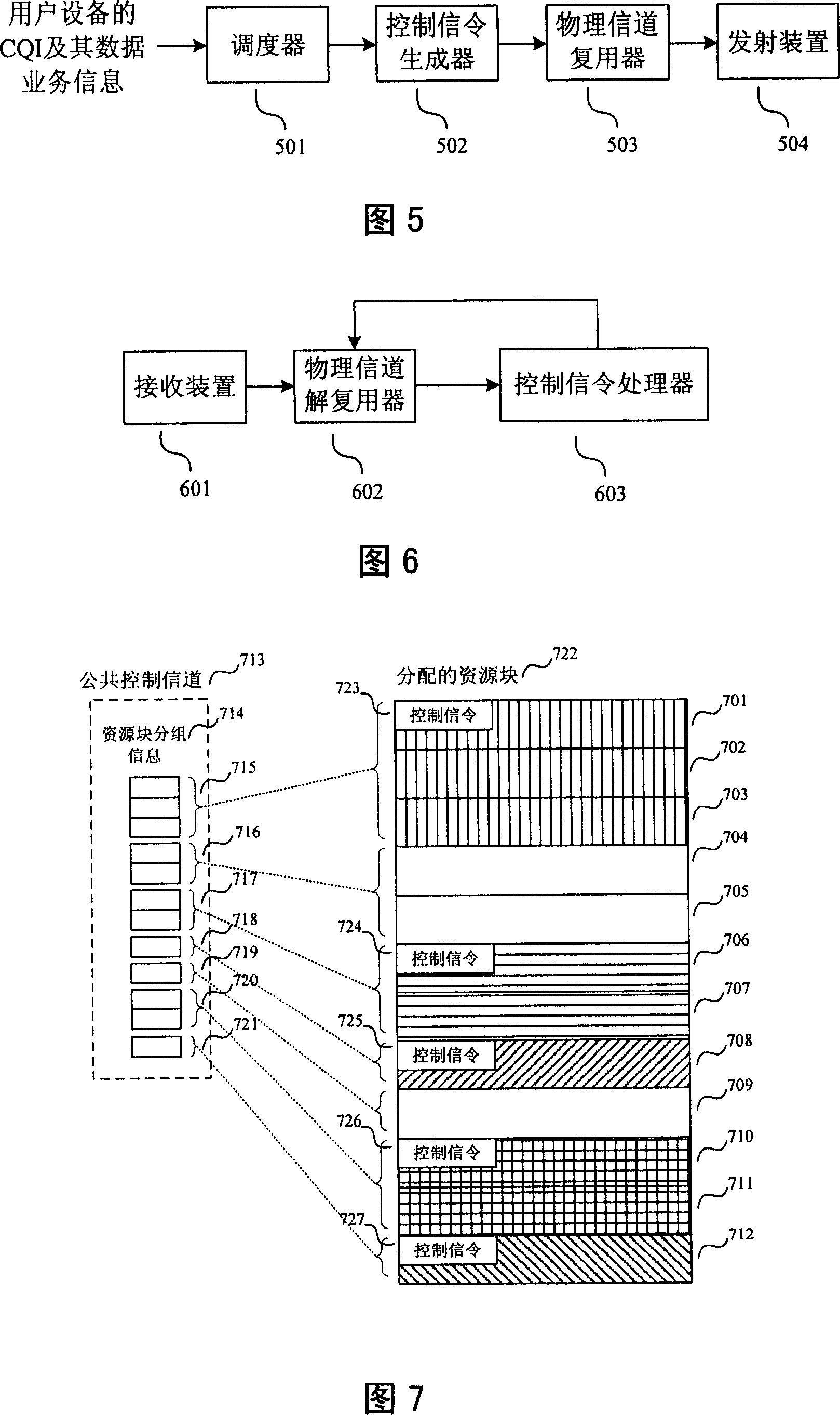
[0084] In this embodiment, the network sends the continuous grouping information of the currently allocated resource blocks on the common control channel; and the network sends the user equipment identification and other control signaling allocated to the resource blocks in each group of resource blocks respectively. It is assumed here that the resource blocks allocated by the network to the user equipment are allocated consecutively.
[0085] In the example shown in FIG. 7 , the number of resource blocks that can be allocated in the network is N=12. The network allocates resource blocks 701, 702 and 703 to user equipment 1, resource blocks 706 and 707 to user equipment 2, resource blocks 708 to user equipment 3, resource blocks 710 and 711 to user equipment 4, and Resource blocks 712 are allocated to user equipment 5 . Resource blocks 704, 705 and 709 are not allocated in the current subframe. In this way, the number of consecutive groupings of resource blocks is M=7, and r...
no. 2 example
[0090] In this embodiment, the network sends the continuous grouping information of the currently allocated resource blocks on the common control channel; and the network sends the user equipment identification and other control signaling allocated to the resource blocks in each group of resource blocks respectively. It is assumed here that the resource blocks allocated by the network to the user equipment may be discontinuous.
[0091] In the example shown in FIG. 8 , the number of resource blocks that can be allocated in the network is N=12. The network allocates resource blocks 801, 802, 803, 810 and 811 to user equipment 1, resource blocks 806 and 807 to user equipment 2, resource blocks 808 and 812 to user equipment 3, resource blocks 804, 805 and 809 Not allocated in the current subframe. In this way, the number of consecutive groupings of resource blocks is M=7, resource blocks 801, 802 and 803 are a group (815), resource blocks 804 and 805 are a group (816), which is ...
PUM
 Abstract
Description
Claims
Application Information
 - R&D
- Intellectual Property
- Life Sciences
- Materials
- Tech Scout
- Unparalleled Data Quality
- Higher Quality Content
- 60% Fewer Hallucinations
Browse by: Latest US Patents, China's latest patents, Technical Efficacy Thesaurus, Application Domain, Technology Topic, Popular Technical Reports.
© 2025 PatSnap. All rights reserved.Legal|Privacy policy|Modern Slavery Act Transparency Statement|Sitemap|About US| Contact US: help@patsnap.com