Power supply linking operation device and operation method

A technology of power supply and operating device, which is applied in the direction of electric light source, lighting device, electroluminescent light source, etc.

Inactive Publication Date: 2008-02-06
BEYOND INNOVATION TECH
View PDF1 Cites 4 Cited by
  • Summary
  • Abstract
  • Description
  • Claims
  • Application Information

AI Technical Summary

Problems solved by technology

[0004] In addition, the applicant disclosed in the previous application US Patent No. 10 / 904,546 that the interlock protection device is only suitable for fluorescent tubes, but not for light-emitting diodes (LEDs); therefore, another interlock operation device is required

Method used


Image

  • Power supply linking operation device and operation method
  • Power supply linking operation device and operation method
  • Power supply linking operation device and operation method

Examples


Embodiment Construction

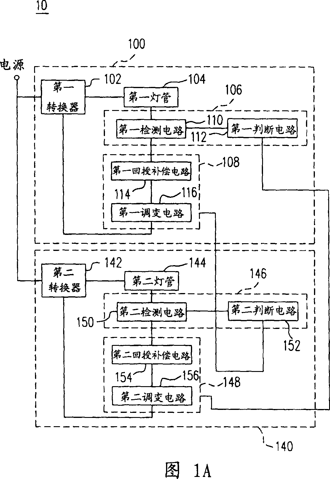
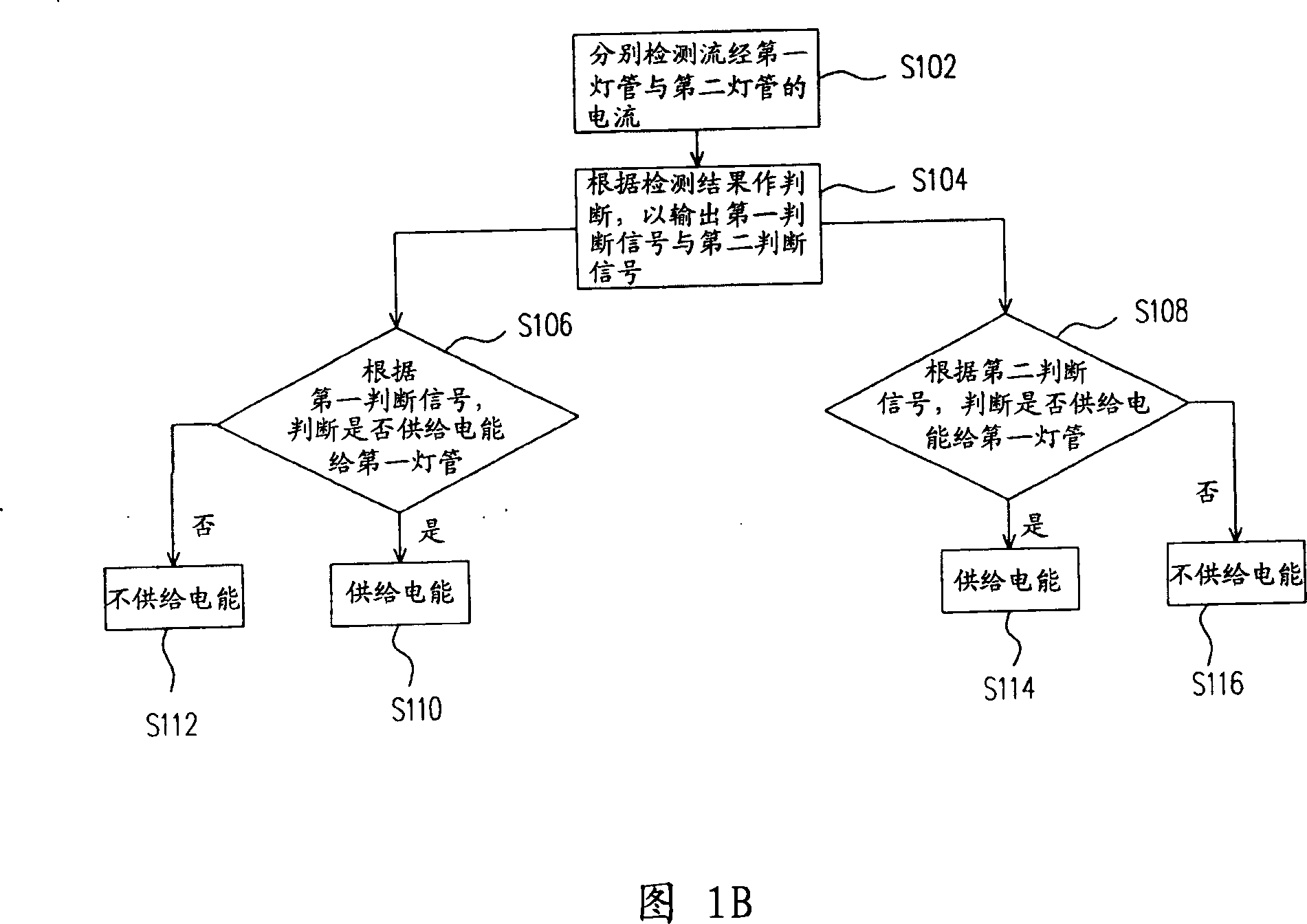
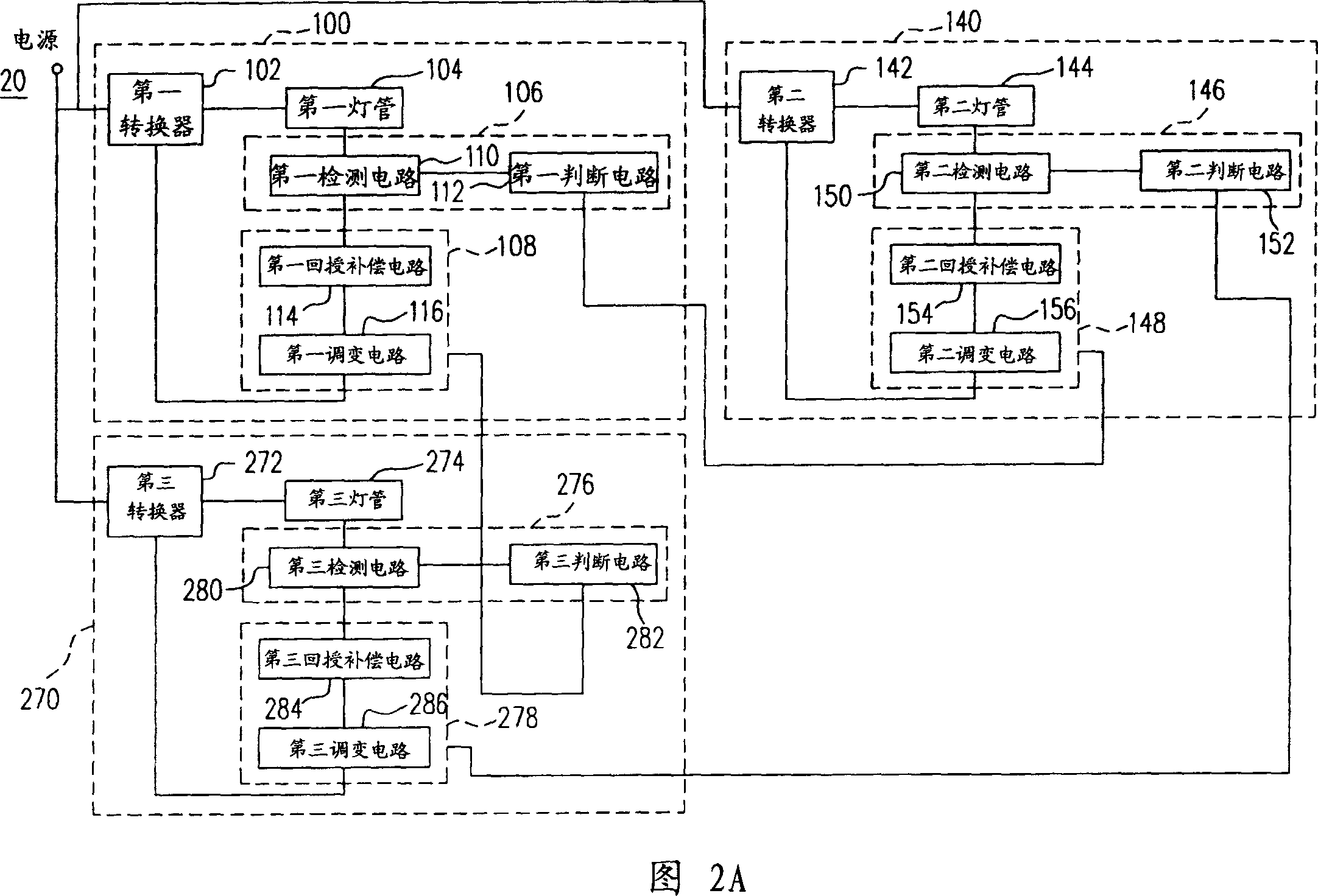
[0100] Since FIGS. 1-4 are special variant embodiments of FIGS. 5A-5D , the more extensive and generalized FIGS. 5A-5D are introduced first. Please refer to FIG. 5A , which discloses a circuit block diagram representing a linkage operation device for two power supplies according to the first embodiment of the present invention. The two-power supply linkage operation device 50 for driving loads includes a first power supply 500 and a second power supply 540 . And the first power supply 500 for driving the first load 504 further includes a first control circuit 508 , a first converter 502 and a first detection module 506 . The first converter 502, such as a DC / DC converter or a DC / AC converter, is coupled to an input power source (not shown in the figure) and the first load 504, wherein the first load 504 may be a set of LED or fluorescent tubes.

[0101] In addition, the second power supply 540 for driving a second load 544 includes a second control circuit 548 , a second con...


PUM


Abstract

A lamp duplexing protection apparatus comprises a first lamp module and a second lamp module. The first lamp module outputs a first decision signal according to whether the first lamp operates normally. The second lamp module outputs a second decision signal according to an operating status of the second lamp. The first lamp module determines whether to supply power to the first lamp according to the second decision signal. The second lamp module determines whether to supply power to the second lamp according to the first decision signal.

Description

technical field [0001] The present invention relates to a power supply for a lighting device and its operating method, and in particular to a power supply linkage operating device and its operating method. Background technique [0002] Due to the popularization and application of liquid crystal displays, fluorescent lamps (Fluorescent Lamp, FL for short) have been widely used in the backlight system of liquid crystal displays (LCD for short), because fluorescent lamps have higher luminous efficiency and service life than traditional fluorescent lamps , and with the maturity of liquid crystal display technology and continuous breakthroughs in product quantification technology, and because liquid crystal displays continue to develop towards large sizes, the application of multi-lamp tubes is gradually moving towards a more complex direction. [0003] Due to the application system of multiple light-emitting devices, multiple power supplies (each of which includes its own contro...

Claims


Application Information

Patent Timeline
Patent Type & Authority Applications(China)
IPC IPC(8): H05B41/14H05B33/08H05B37/02H05B44/00
Inventor 黄世中
Owner BEYOND INNOVATION TECH
Why Eureka
Try Eureka